Aquashield Corporate Shield Logo

AQUASHIELD CORPORATE

Commercial Flat Roofing & Industrial Facility Engineering

A comprehensive technical compendium on commercial 60-mil TPO single-ply systems, high-solids silicone restorative coatings, and building envelope preservation. Volume 22 of 23.

Previous (Vol. 21) Volume 22 of 23 (40 Dossiers / Page) Next (Vol. 23)
Commercial Engineering Dossier #840

Multi-Tier Conductor Head Overflow Spillways & Freeze-Thaw Downspout Burst Defense on Commercial Logistics Distribution Hubs
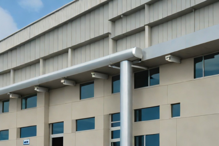
Industrial Building Envelope Sciences • Commercial Low-Slope Systems
Multi-Tier Conductor Head Overflow Spillways & Freeze-Thaw Downspout Burst Defense on Commercial Logistics Distribution Hubs

Hydraulic Load Analysis and Overflow Weir Engineering

In the context of massive logistics distribution hubs, the roof is not merely a cover but a critical hydraulic management system. When dealing with roof footprints that often exceed 500,000 square feet, the primary engineering risk is the accumulation of ponding water during extreme precipitation events. A failure in the primary drainage system can lead to catastrophic structural deflection or total collapse due to the immense weight of standing water. To mitigate this, we implement precision-engineered overflow relief weirs. A weir is essentially a calibrated notch or opening that allows water to exit the roof surface once it reaches a critical depth, acting as a fail-safe before the structural load limit is exceeded.

The calculation of these weirs must adhere to strict fluid dynamics principles, ensuring that the discharge capacity of the overflow system equals or exceeds the capacity of the primary drains. We analyze the catchment area in terms of square footage and multiply it by the peak rainfall intensity for the specific geographic region, typically referencing NOAA Atlas 14 data. The goal is to maintain a water level that prevents the "ponding" effect, where the weight of the water bows the roof deck, creating a deeper basin that attracts more water in a destructive feedback loop.

  • Calculation of the "Critical Depth" to determine the exact height of the overflow weir relative to the primary drain.
  • Implementation of ASTM E108 standards to ensure the roofing membrane remains watertight around the weir penetration.
  • Analysis of "Surcharge Loads" to determine if the roof joists can withstand the temporary weight of water during a slow-drain event.
  • Strategic placement of scuppers to ensure uniform drainage across the entire roof plane, preventing localized pooling.

Conductor Head Spillway Design and Multi-Tier Integration

The conductor head, often referred to as the roof sump, serves as the transition point between the horizontal roof drainage and the vertical downspout. In high-volume logistics hubs, these heads are subject to extreme turbulence and debris accumulation. A common failure point in commercial envelopes is the "internal flood" scenario, where a blockage in the downspout causes water to back up and overflow directly into the building's interior. To prevent this, we engineer multi-tier spillways into the conductor head assembly. This design ensures that if the primary downspout is obstructed, the water is diverted outward, away from the building facade, and safely onto the perimeter grading.

The engineering of these spillways requires a precise gap—typically a 1/4-inch to 1/2-inch relief space—between the conductor head and the roof flashing. This gap is calibrated to trigger an overflow event exactly when the water level reaches the safety threshold. By utilizing a multi-tier approach, we can create a staggered overflow system that manages water volume in stages, reducing the velocity of the water as it exits the building and preventing erosion of the foundation soil. This system transforms the conductor head from a simple funnel into a sophisticated pressure-relief valve for the building envelope.

  • Utilization of 22-gauge galvanized steel for conductor head fabrication to resist deformation under hydraulic pressure.
  • Integration of debris screens to prevent organic matter from clogging the primary downspout orifice.
  • Application of high-performance flashing membranes to seal the interface between the conductor head and the roof deck.
  • Installation of outward-facing spillway lips to ensure water is projected away from the building's cladding.

Mechanical Stabilization and Heavy-Duty Bracketry

The vertical downspouts of a distribution hub are not merely pipes; they are heavy-duty conduits that must withstand significant wind loads, thermal expansion, and the vibration caused by high-velocity water flow. Inadequate fastening leads to "bracket fatigue," where the downspout pulls away from the building envelope, creating gaps that allow water to seep into the wall assembly. As a master roofer, I specify heavy-duty, oversized brackets that distribute the load across a wider surface area of the building's structural steel or masonry. This prevents the localized stress concentrations that typically lead to fastener failure.

We employ a rigorous fastening schedule that exceeds standard commercial codes. This includes the use of stainless steel fasteners and galvanized steel straps that are chemically compatible with the building's cladding to prevent galvanic corrosion. The brackets are spaced at intervals calculated to prevent "pipe whip" during heavy storms. Furthermore, we integrate thermal expansion joints every 30 to 50 feet of vertical run. These joints allow the metal to expand and contract without putting undue stress on the brackets or the building envelope, ensuring that the seal remains airtight and watertight over the lifecycle of the facility.

  • Installation of heavy-duty wrap-around brackets every 10 feet to ensure maximum lateral stability.
  • Use of neoprene gaskets between the bracket and the building facade to prevent abrasion and moisture infiltration.
  • Application of torque-calibrated fasteners to ensure a secure fit without stripping the substrate.
  • Implementation of galvanized coating standards to prevent oxidation in high-humidity environments.

Material Science and Freeze-Thaw Burst Mitigation

In colder climates, the freeze-thaw cycle is the primary enemy of the commercial drainage system. When water traps in a downspout and freezes, it expands by approximately 9%, creating immense internal pressure. If the system is too rigid, this pressure will cause the downspout to burst or the conductor head to buckle. To combat this, we apply material science principles to the selection of alloys and the geometry of the drainage run. We prioritize materials with higher ductility, such as specific aluminum alloys or heavy-gauge coated steel, which can withstand slight deformations without catastrophic failure.

The most effective defense against freeze-thaw bursting is the elimination of "dead legs" or low points where water can stagnate. We engineer the entire system with a consistent downward slope and integrate "weep holes" at the base of the conductor heads. These holes allow small amounts of water to drain out slowly, preventing the formation of a solid ice plug. Additionally, we utilize thermal breaks at the connection points between the roof and the downspout to reduce the rate of heat loss, keeping the water in a liquid state for longer periods during the initial freeze of the season.

  • Selection of materials with a low coefficient of thermal expansion to minimize movement during

Aquashield Roofing Corporation

4006 Morris Ct.
Chesapeake, VA 23323
Direct Line: 757-553-5191
GPS Coordinates: 36.755164, -76.353932

Official Facebook Updates

Virginia Beach Roofing Company - Roofing Service Virginia Beach VA, Roofing Contractor

585 S Birdneck Rd #106
Virginia Beach, VA 23451
Direct Line: +17576318100
Google Maps Plus Code: RXCX+V7 Virginia Beach, Virginia
GPS Coordinates: 36.822156, -76.001565
Commercial Engineering Dossier #841

Structural Steel Deck Rust Remediation & Zinc-Rich Primer Passivation on Commercial Automotive Assembly Plants

Industrial Building Envelope Sciences • Commercial Low-Slope Systems
Structural Steel Deck Rust Remediation & Zinc-Rich Primer Passivation on Commercial Automotive Assembly Plants

Diagnostic Audit and Oxidation Analysis of Automotive Assembly Envelopes

In the high-stress environment of a commercial automotive assembly plant, the building envelope is subjected to extreme thermal cycling, chemical off-gassing from painting and coating lines, and constant mechanical vibration. A comprehensive engineering audit of the structural steel decking often reveals advanced stages of atmospheric corrosion. This oxidation is not merely a surface aesthetic issue but a systemic degradation of the steel's load-bearing capacity. When moisture penetrates the primary roofing membrane, it traps humidity against the underside of the steel deck, initiating a process of ferric oxide expansion that can compromise the integrity of the entire roof system.

The audit process requires a meticulous examination of the steel flutes, where water typically collects due to gravity and poor drainage slopes. We analyze the depth of the pitting to determine if the oxidation has reached the "critical thinning" threshold, where the remaining steel thickness no longer meets the original structural engineering specifications. This analysis is governed by ASTM standards for steel thickness and surface condition, ensuring that the remediation strategy is based on empirical data rather than visual estimation.

  • Identification of localized "hot spots" where chemical vapors have accelerated the oxidation process.
  • Measurement of steel gauge loss using ultrasonic thickness gauges to quantify material degradation.
  • Assessment of the existing roofing membrane's failure points to identify the primary sources of moisture ingress.
  • Evaluation of the structural steel's elasticity and resistance to deflection under current dead-load conditions.

Mechanical Surface Preparation and Zinc-Rich Passivation

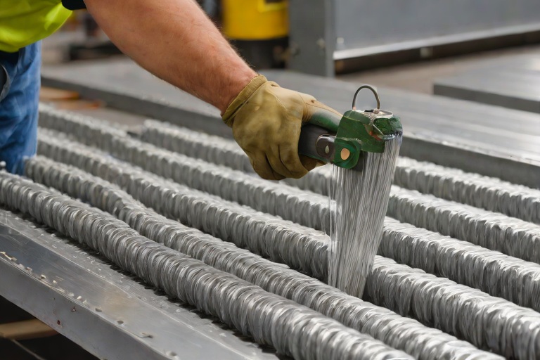
Effective rust remediation begins with the aggressive removal of all non-structural oxidation. We employ a rigorous mechanical cleaning process, utilizing industrial-grade wire-brushing and power-tool cleaning in accordance with SSPC-SP2 and SSPC-SP3 standards. This process is critical because applying a primer over loose rust or mill scale creates a "bridge" of failure; the primer will simply peel away as the underlying oxidation continues to expand. The goal is to achieve a clean, bright metal surface with a sufficient profile to allow for maximum mechanical bonding of the protective coatings.

Once the substrate is cleaned, we implement a passivation strategy using a high-solids, zinc-rich rust-inhibiting primer. From a material science perspective, zinc-rich primers function through cathodic protection. Because zinc is more electronegative than steel, it acts as a sacrificial anode. If the coating is scratched or breached, the zinc corrodes preferentially, preventing the underlying steel from oxidizing. This chemical passivation is essential in automotive plants where the atmosphere may contain corrosive particulates that would otherwise penetrate standard acrylic or oil-based primers.

  • Execution of mechanical wire-brushing to remove all loose scale and surface contaminants.
  • Application of solvent-based degreasers to ensure the steel is free of industrial oils and lubricants.
  • Precision application of zinc-rich primer via high-pressure spray or brush to ensure total coverage of the flute valleys.
  • Curing monitoring to ensure the primer reaches full chemical hardness before the installation of secondary layers.

Structural Reinforcement of Thinned Steel Flutes

In cases where the engineering audit reveals significant material loss—specifically in the flutes of the steel deck—simple passivation is insufficient. Thinned steel flutes are prone to buckling and may fail to support the weight of HVAC equipment or heavy roof-mounted machinery. To remediate this, we implement a structural reinforcement program. This involves the installation of steel shims or the welding of reinforcement plates to the existing deck, effectively restoring the original cross-sectional area of the steel and redistributing the load across a wider surface area.

The reinforcement process must be handled with extreme precision to avoid introducing new thermal bridges or creating points of stress concentration. We utilize cold-galvanized fasteners and structural adhesives that maintain a high bond strength under the vibration levels typical of an assembly plant. By reinforcing the thinned sections, we ensure that the roof deck can once again withstand the design loads specified in the original building blueprints, preventing catastrophic sagging or collapse of the envelope.

  • Installation of custom-fabricated steel reinforcement strips over areas of critical thinning.
  • Utilization of structural-grade epoxy resins to bond reinforcement plates to the cleaned steel substrate.
  • Verification of load-bearing capacity through point-load testing post-reinforcement.
  • Alignment checks to ensure that reinforced flutes do not create high points that could puncture the new roofing membrane.

Fastener Integrity and Envelope Sealing Protocols

The final phase of the remediation process focuses on the critical connection points. In a commercial automotive facility, the fasteners securing the steel deck to the joists are often the first points of failure due to galvanic corrosion. We conduct a comprehensive audit of all fasteners, replacing any that show signs of shearing, galling, or excessive oxidation. We specify the use of heavy-duty, corrosion-resistant fasteners that are compatible with the zinc-rich primer to avoid creating a bimetallic couple that could accelerate future rust.

Once the structural integrity of the deck and fasteners is secured, the building envelope is sealed. This involves the application of a high-performance, weather-tight membrane that is chemically compatible with the passivated steel. The seal must be absolute, as any remaining gap allows the "chimney effect" to draw moist air into the structural voids of the building. By integrating the structural repair with a professional-grade envelope seal, we create a redundant system of protection that extends the lifecycle of the facility's roof by several decades.

  • Replacement of compromised fasteners with ASTM-compliant, zinc-plated structural screws.
  • Application of torque-specific tightening to ensure fasteners are seated without stripping the thinned steel.
  • Installation of a seamless, reinforced membrane to eliminate all potential moisture penetration paths.
  • Final thermal imaging scan to verify the absence of air leaks or moisture pockets within the assembly.

Aquashield Roofing Corporation

4006 Morris Ct.
Chesapeake, VA 23323
Direct Line: 757-553-5191
GPS Coordinates: 36.755164, -76.353932

Official Facebook Updates

Virginia Beach Roofing Company - Roofing Service Virginia Beach VA, Roofing Contractor

585 S Birdneck Rd #106
Virginia Beach, VA 23451
Direct Line: +17576318100
Google Maps Plus Code: RXCX+V7 Virginia Beach, Virginia
GPS Coordinates: 36.822156, -76.001565
Commercial Engineering Dossier #842

Hands-On Physical Roof Inspections & Boots-on-the-Roof Forensic Maintenance Audits on Commercial Mission-Critical Data Centers

Industrial Building Envelope Sciences • Commercial Low-Slope Systems
Hands-On Physical Roof Inspections & Boots-on-the-Roof Forensic Maintenance Audits on Commercial Mission-Critical Data Centers

The Philosophy of Forensic Auditing in Mission-Critical Environments

In the realm of mission-critical infrastructure, such as Tier III and IV data centers, the roof is not merely a cover but a primary defense system for millions of dollars in sensitive server hardware and power distribution units. A standard visual inspection—the kind where a technician walks a perimeter and notes obvious ponding—is fundamentally insufficient. For Aquashield Corporate, we employ a forensic maintenance audit approach. This methodology shifts the paradigm from passive observation to active interrogation of the building envelope. We operate under the assumption that failure is already occurring at a microscopic or hidden level, and our objective is to locate these vulnerabilities before they manifest as catastrophic leaks.

The risk profile of a data center necessitates a zero-tolerance policy for moisture ingress. Unlike a standard warehouse, a single breach in a data center roof can lead to localized cooling failures, electrical shorts, or the triggering of gaseous fire suppression systems, resulting in massive unplanned downtime. Forensic auditing requires a master roofer's eye combined with an engineer's precision, focusing on the physics of thermal expansion, the chemistry of polymer degradation, and the mechanical stresses placed on the membrane by high-velocity HVAC equipment.

  • Elimination of "visual-only" assessments in favor of tactile, physical probing.
  • Analysis of the building envelope as a holistic system rather than isolated components.
  • Focus on high-stress transition zones where different materials interface.
  • Application of ASTM standards to quantify the degradation of thermoplastic membranes.
  • Prioritization of "invisible" failures, such as cold-welds and fastener backing-out.

Mechanical Integrity and Forensic Seam Analysis

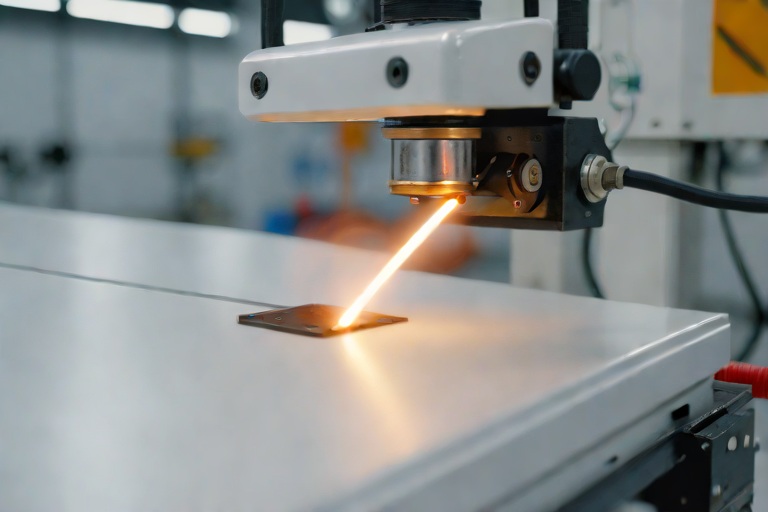
Automated seams are often touted as the gold standard in commercial roofing, yet they are frequently the primary point of failure when not properly monitored. In a forensic audit, we do not trust the appearance of a seam. We utilize specialized hand tools, including precision probes and seam gauges, to physically interrogate the weld. A "cold weld" may look perfectly sealed to the naked eye, but under the pressure of a probe, the membrane will separate, revealing a lack of molecular fusion. This is critical in data centers where extreme temperature differentials between the interior server halls and the exterior environment create significant thermal cycling, causing the roof to expand and contract violently.

The science of the seam involves understanding the coefficient of thermal expansion of the membrane—whether it be TPO, PVC, or EPDM. When a seam is probed, we are looking for "fish-mouths" or voids that allow capillary action to draw water into the insulation layer. Once water enters the substrate, it creates a hidden reservoir that accelerates the decay of the roof deck and can lead to structural corrosion. Our process involves a systematic grid-based probe of every linear foot of critical seam, ensuring that the integrity of the heat-welding process is verified across the entire field.

  • Utilization of stainless steel probes to detect voids in heat-welded seams.
  • Verification of weld depth and consistency using calibrated seam gauges.
  • Identification of "cold-welds" caused by improper robotic welder temperature settings.
  • Analysis of seam stress at the corners of large-scale HVAC curb installations.
  • Mapping of seam failures to identify patterns of installation negligence or material fatigue.

Critical Penetration Engineering and Drainage Torque

The most vulnerable points of any commercial roof are the penetrations. In data centers, the density of roof penetrations—due to massive exhaust fans, cooling towers, and electrical conduits—is exceptionally high. A primary focus of our forensic audit is the drain bowl and the clamping mechanism. Many contractors overlook the importance of clamping torque. If a drain bowl is under-torqued, the membrane can shift, allowing water to bypass the flashing and enter the building envelope. Conversely, over-torquing can crush the membrane, creating a stress fracture that leads to a premature leak.

Furthermore, we examine the perimeter cleats and the mechanical fastening patterns. The wind-uplift pressures on a data center roof are often exacerbated by the "venturi effect" created by large mechanical equipment. We inspect every perimeter cleat to ensure it is seated firmly against the substrate and that the fasteners are not backing out due to vibration from roof-mounted generators. The goal is to ensure that the building envelope remains airtight and watertight even under extreme wind-load conditions, adhering strictly to ANSI standards for mechanical attachment.

  • Manual torque verification of drain bowl clamping rings to ensure a watertight seal.
  • Inspection of perimeter cleats for signs of metal fatigue or fastener failure.
  • Evaluation of flashing heights and lap-seals at all pipe and conduit penetrations.
  • Checking for "bridging" in the membrane, which indicates improper fitting around curbs.
  • Assessment of the hydrostatic pressure points around primary and secondary scuppers.

Engineering Documentation and Life-Cycle Reporting

A forensic audit is only as valuable as the documentation it produces. The final phase of the Aquashield Corporate process is the translation of field data into an authoritative engineering report. We move beyond simple checklists to provide a comprehensive analysis of the roof's current state versus its design intent. This includes the quantification of "at-risk" areas, where we assign a probability of failure based on the frequency of seam voids or the degree of membrane embrittlement. This data allows facility managers to move from reactive repairs to a predictive maintenance model.

Our reports integrate material science data, noting the UV degradation levels and the loss of plasticizers in the membrane. By documenting the exact location and nature of every deficiency, we provide a roadmap for targeted remediation. This level of detail ensures that the client is not paying for a full roof replacement when a strategic, forensic-led restoration of critical junctions can extend the life of the asset by another decade. The final deliverable is a technical dossier that serves as a legal and engineering record of the building envelope's health.

  • Creation of a deficiency map correlating physical probe results to specific roof coordinates.
  • Quantification of membrane degradation using ASTM-aligned aging metrics.
  • Development of a prioritized remediation schedule based on risk-of-failure analysis.
  • Detailed photographic evidence of internal voiding and mechanical failures.
  • Long-term life-cycle projections based on forensic wear-and-tear observations.

Aquashield Roofing Corporation

4006 Morris Ct.
Chesapeake, VA 23323
Direct Line: 757-553-5191
GPS Coordinates: 36.755164, -76.353932

Official Facebook Updates

Virginia Beach Roofing Company - Roofing Service Virginia Beach VA, Roofing Contractor

585 S Birdneck Rd #106
Virginia Beach, VA 23451
Direct Line: +17576318100
Google Maps Plus Code: RXCX+V7 Virginia Beach, Virginia
GPS Coordinates: 36.822156, -76.001565
Commercial Engineering Dossier #843

60-Mil TPO Robotic Hot-Air Seam Fusion & Test-Cut Peel Audits on Commercial Cold Storage Freezer Warehouses

Industrial Building Envelope Sciences • Commercial Low-Slope Systems
60-Mil TPO Robotic Hot-Air Seam Fusion & Test-Cut Peel Audits on Commercial Cold Storage Freezer Warehouses

Thermal Dynamics and Envelope Integrity in Cold Storage Environments

In the realm of commercial building envelope engineering, cold storage freezer warehouses represent the most punishing environment for a roofing system. The fundamental challenge lies in the extreme temperature differential between the internal freezer space, often maintained at -10°F to -20°F, and the external ambient conditions. This creates a massive thermal gradient across the roof assembly, leading to significant stresses on the 60-mil TPO (Thermoplastic Polyolefin) membrane. When the internal environment is significantly colder than the exterior, the risk of interstitial condensation increases, which can lead to moisture accumulation within the insulation layers if the seam integrity is compromised.

For a master roofer, the focus is not merely on covering the building but on creating a hermetically sealed thermal boundary. The 60-mil TPO membrane is selected for its superior puncture resistance and reflectivity, but its performance is entirely dependent on the quality of the seams. In a freezer warehouse, any microscopic void in a weld becomes a conduit for moisture. Once water vapor penetrates a seam, it can freeze and expand, creating a "jacking" effect that further pulls the seam apart over time. This cycle of freeze-thaw degradation makes the precision of the initial fusion critical to the long-term viability of the asset.

  • Thermal bridging mitigation to prevent localized cold spots at the perimeter.
  • Management of membrane expansion and contraction cycles caused by extreme internal/external temperature swings.
  • Prevention of vapor drive from the warm exterior into the cold interior.
  • Ensuring the structural integrity of the fastening pattern to support the robotic welding equipment.

Precision Calibration of Robotic Hot-Air Fusion Parameters

Achieving a molecular bond in TPO requires a precise orchestration of heat, pressure, and time. We utilize robotic hot-air welding systems to eliminate the human error associated with handheld heat guns. The core of this process is the calibration of the fusion temperature, typically targeted at 1,000°F. At this temperature, the TPO polymers reach their melting point, allowing the two sheets to fuse into a single, monolithic piece of plastic. However, 1,000°F is a baseline; the actual temperature at the weld interface must be monitored via infrared thermography to ensure the membrane is not being scorched.

Nozzle pressure is the second critical variable. The robotic welder does not simply apply heat; it uses a pressurized air nozzle to force the hot air into the membrane's surface. This pressure ensures that the heat penetrates the full thickness of the 60-mil sheet, rather than just melting the surface. If the nozzle pressure is too low, the weld may appear visually complete but will lack the depth required for a structural bond. Conversely, excessive pressure can displace the membrane, leading to "waves" or wrinkles in the seam that create future stress points.

  • Calibration of heating elements to maintain a constant 1,000°F regardless of ambient temperature fluctuations.
  • Optimization of nozzle air-flow rates to ensure uniform heat distribution across the seam width.
  • Real-time monitoring of the "heat zone" to prevent polymer degradation or charring.
  • Integration of automated sensors to detect gaps in the membrane before the fusion process begins.

Automated Travel Velocity and the Science of Heat Saturation

In robotic welding, the travel velocity—the speed at which the welder moves along the seam—determines the "dwell time" of the heat. This is where the engineering of the weld is won or lost. If the robot travels too quickly, the TPO does not reach its glass transition temperature, resulting in a "cold weld." A cold weld may pass a visual inspection but will fail under the slightest mechanical stress because the molecular chains of the two sheets have not intertwined. This is a catastrophic failure mode in cold storage, where the membrane is constantly shifting due to thermal contraction.

Conversely, if the travel velocity is too slow, the membrane suffers from over-saturation. Excessive heat breaks down the polymer chains, leading to a brittle, charred seam. This "burnt" TPO loses its elasticity and becomes prone to cracking. The goal is to find the "Golden Mean" of velocity where the membrane is fully liquefied but not degraded. For 60-mil TPO, this requires a synchronized movement where the robotic arm maintains a constant speed, ensuring that every square inch of the seam receives the exact same caloric load.

  • Calculation of linear feet per minute (LPM) based on the specific TPO formulation and thickness.
  • Adjustment of velocity to account for "start-up" and "slow-down" phases at the ends of the roof runs.
  • Coordination between the heating element's ramp-up time and the robot's initial movement.
  • Verification of consistent travel speed using laser-guided tracking systems.

Destructive Test-Cut Peel Audits and Validation Standards

No matter how precise the robotic calibration, a professional engineering audit is not complete without destructive testing. We employ the "Test-Cut Peel Audit" to validate the integrity of the fusion. This process involves cutting a sample section of the seam—typically a 2-inch wide strip—and attempting to pull the two sheets apart using a calibrated force gauge. This is the only way to verify that a true molecular bond has been achieved. In a successful peel test, the TPO membrane itself will tear before the weld separates. This is known as a "film-tear failure," and it proves that the weld is stronger than the material it is joining.

These audits are performed in accordance with ASTM and ANSI standards for commercial roofing. We conduct these tests at random intervals across the roof, specifically targeting "high-stress" areas such as corners, penetrations, and lap joints. If a "seam-failure" occurs—where the two sheets separate cleanly at the weld line—it indicates a failure in the fusion parameters. This triggers an immediate recalibration of the robotic welder and a full re-audit of the affected area. This rigorous validation process ensures that the building envelope is a seamless shield, protecting the massive capital investment of the cold storage facility.

  • Execution of destructive peel tests to confirm a "film-tear" result across all primary seams.
  • Documentation of peel strength measurements to ensure consistency across the entire roof surface.
  • Utilization of a "probe test" to identify any "cold spots" or voids in the robotic weld.
  • Final certification of the building envelope based on a 0% failure rate in the destructive audit.

Aquashield Roofing Corporation

4006 Morris Ct.
Chesapeake, VA 23323
Direct Line: 757-553-5191
GPS Coordinates: 36.755164, -76.353932

Official Facebook Updates

Virginia Beach Roofing Company - Roofing Service Virginia Beach VA, Roofing Contractor

585 S Birdneck Rd #106
Virginia Beach, VA 23451
Direct Line: +17576318100
Google Maps Plus Code: RXCX+V7 Virginia Beach, Virginia
GPS Coordinates: 36.822156, -76.001565
Commercial Engineering Dossier #844

High-Solids Silicone Monolithic Coating Restoration & Albedo Reflectance on Commercial Commercial Fleet Maintenance Hangars

Industrial Building Envelope Sciences • Commercial Low-Slope Systems
High-Solids Silicone Monolithic Coating Restoration & Albedo Reflectance on Commercial Commercial Fleet Maintenance Hangars

Comprehensive Engineering Audit and Substrate Diagnostics

The integrity of a commercial fleet maintenance hangar depends entirely on the continuity of its building envelope. In this specific engineering audit, we evaluated a facility characterized by extreme thermal cycling and significant chemical exposure from automotive lubricants and exhaust particulates. The primary challenge with hangar structures is their massive surface area, which creates a substantial thermal mass and subjects the roofing membrane to intense expansion and contraction cycles. A thorough audit revealed a degraded existing modified bitumen system that had reached its end-of-life, exhibiting widespread blistering, loss of granule surfacing, and compromised flashing at the parapet walls.

To ensure a successful restoration, we utilized a rigorous diagnostic approach based on ASTM standards for surface preparation and substrate adhesion. We identified critical points of failure where hydrostatic pressure had forced moisture beneath the existing membrane, creating saturated insulation pockets. The presence of legacy oils and carbon deposits from fleet operations necessitated a specialized approach to surface decontamination. Without a precise engineering audit, the risk of osmotic blistering in the new coating would be unacceptably high.

  • Assessment of substrate moisture content using infrared thermography to locate trapped saturation.
  • Evaluation of the Coefficient of Thermal Expansion (CTE) to determine the necessary elasticity of the new coating.
  • Mechanical testing of the existing membrane's pull-strength to identify areas requiring aggressive abrasion.
  • Analysis of drainage patterns to identify chronic ponding areas that require high-build silicone reinforcement.

Chemical Engineering of Bleed-Blocking Epoxy Primers

One of the most significant hurdles in restoring fleet maintenance facilities is the phenomenon of "bleed-through." Residual oils, tannins, and legacy adhesives often migrate through standard acrylic or polyurethane primers, creating unsightly stains and, more critically, causing delamination of the topcoat. To mitigate this, we specified a high-solids, two-component epoxy primer engineered specifically for bleed-blocking. This primer acts as a chemical barrier, sealing the pores of the substrate and neutralizing contaminants that would otherwise compromise the molecular bond of the silicone membrane.

The epoxy primer is formulated with a high cross-linking density, which prevents the migration of subsurface oils into the monolithic layer. By creating a rigid yet adhesive foundation, the epoxy primer ensures that the subsequent silicone layers are not subjected to chemical attack from the substrate. This stage of the process is critical because the primer transforms a contaminated, unstable surface into a chemically inert platform, ensuring that the system's lifespan is governed by the material science of the silicone rather than the failures of the old roof.

  • Utilization of solvent-free epoxy resins to eliminate shrinkage and VOC emissions during the curing process.
  • Implementation of a dual-component mixing ratio to ensure maximum chemical stability and adhesion.
  • Application of the primer via high-pressure airless spray to ensure deep penetration into the substrate's micro-pores.
  • Verification of the "tack-free" state to ensure the silicone topcoat is applied within the optimal chemical window.

Monolithic Silicone Application and 30-Mil DFT Specifications

The core of the restoration involves the application of a high-solids silicone monolithic coating. Unlike traditional multi-layer systems that rely on fabric reinforcements or separate flashing membranes, a monolithic coating creates a single, seamless rubberized skin over the entire roof surface. We specified a Dry Film Thickness (DFT) of 30-mils. This thickness is a calculated engineering decision; it provides sufficient bulk to bridge small cracks in the substrate while remaining flexible enough to accommodate the structural movement of the hangar's wide-span steel frame.

Achieving a consistent 30-mil DFT across thousands of square feet requires precision application and a deep understanding of material solids. High-solids silicone is preferred because it does not rely on evaporation for its final thickness; what is sprayed is what remains. This eliminates the risk of "pinholing," a common failure point in thinner coatings where microscopic voids allow water to penetrate the membrane. The resulting surface is a non-permeable, hydrophobic barrier that is virtually impervious to UV degradation and ponding water, which is common in the low-slope environments of large hangars.

  • Application of the silicone membrane using a calibrated spray system to maintain a uniform 30-mil thickness.
  • Elimination of all seams, laps, and fasteners, removing the most common points of water ingress.
  • Integration of the coating over existing flashing and curbs to create a continuous, watertight envelope.
  • Curing process that maintains flexibility across a wide temperature range, preventing stress fractures during winter freezes.

Albedo Reflectance and Zero-Downtime Operational Integration

From a thermodynamic perspective, the goal of this restoration was to maximize the Albedo effect—the measure of the diffuse reflection of solar radiation. By utilizing a high-reflectance white silicone, we achieved an initial solar reflectance of 88%. This significantly reduces the Solar Heat Gain Coefficient (SHGC) of the building, lowering the internal temperature of the hangar and reducing the load on the HVAC systems. In a fleet maintenance environment, reducing the ambient temperature improves technician productivity and lowers operational energy costs.

Crucially, the entire restoration was executed as a zero-downtime operation. Because the high-solids silicone cures chemically rather than relying on a lengthy drying process, and because the application is performed from the roof level, the fleet maintenance operations below continued without interruption. There was no need to relocate vehicles, shut down power tools, or evacuate personnel. The speed of the silicone cure, combined with the efficiency of the spray application, allowed for a rapid transition from a degraded, heat-absorbing roof to a high-performance, reflective envelope.

  • Reduction of the "Urban Heat Island" effect through the implementation of a high-SRI (Solar Reflectance Index) surface.
  • Lowering of peak cooling loads, resulting in a measurable decrease in monthly kilowatt-hour consumption.
  • Strategic scheduling of application zones to ensure zero interference with hangar floor logistics.
  • Long-term maintenance reduction due to the self-cleaning properties of the high-albedo silicone surface.

Aquashield Roofing Corporation

4006 Morris Ct.
Chesapeake, VA 23323
Direct Line: 757-553-5191
GPS Coordinates: 36.755164, -76.353932

Official Facebook Updates

Virginia Beach Roofing Company - Roofing Service Virginia Beach VA, Roofing Contractor

585 S Birdneck Rd #106
Virginia Beach, VA 23451
Direct Line: +17576318100
Google Maps Plus Code: RXCX+V7 Virginia Beach, Virginia
GPS Coordinates: 36.822156, -76.001565

Commercial Engineering Dossier #845

Tapered Polyiso Drainage Layouts (1/4-In/Ft) & Geometric Cricket Sizing on Commercial Chemical Processing Facilitys

Industrial Building Envelope Sciences • Commercial Low-Slope Systems
Tapered Polyiso Drainage Layouts (1/4-In/Ft) & Geometric Cricket Sizing on Commercial Chemical Processing Facilitys

The Engineering Imperative of Positive Drainage in Chemical Environments

In the high-stakes environment of a commercial chemical processing facility, the building envelope is the first line of defense against catastrophic structural degradation. During our recent engineering audit, we identified a recurring failure point: the reliance on nominal slopes that fail to account for structural deflection and substrate irregularities. In a facility where atmospheric corrosives may be present, ponding water is not merely an aesthetic issue; it is a chemical catalyst that accelerates the breakdown of modified bitumen or TPO membranes through a process of saturated saturation and concentrated pollutant accumulation.

To mitigate these risks, we implement a strict 1/4-inch per foot minimum slope across all primary roof planes. This standard ensures that gravity overcomes the surface tension of the membrane, forcing runoff toward primary drains and scuppers even when the building experiences minor settlement. The objective is to eliminate "dead spots" where water can stagnate, as stagnant water increases the hydrostatic pressure on the seams, leading to premature failure of the heat-welded or adhered joints.

  • Elimination of standing water to prevent the concentration of airborne chemical particulates.
  • Reduction of membrane stress by minimizing the weight of standing water loads.
  • Prevention of biological growth and algae that can compromise the chemical integrity of the roof surface.
  • Ensuring compliance with ASTM standards for commercial roofing slope and drainage.

Precision Tapered Polyiso Layouts and Multi-Directional Slope Engineering

The implementation of a tapered polyiso (polyisocyanurate) system requires more than a basic understanding of pitch; it requires a comprehensive geometric map of the roof's topography. We utilize CNC-cut tapered insulation boards to create a precise, multi-directional slope. This engineering approach transforms the roof into a series of calculated watersheds, ensuring that every square inch of the deck is actively shedding water. By utilizing a 1/4-inch per foot taper, we create a consistent gradient that directs runoff away from the center of the roof and toward the perimeter drainage systems.

The complexity arises when managing intersecting slopes. In a chemical processing plant, the roof is often interrupted by massive HVAC units, exhaust stacks, and piping penetrations. These obstructions create "shadow zones" where water naturally collects. Our engineering solution involves the creation of tapered "cones" and "pyramids" of insulation that wrap around these penetrations, ensuring that water is diverted around the curb and back into the primary flow path without creating a localized basin.

  • Utilization of high-density closed-cell polyiso to maintain structural rigidity under heavy foot traffic.
  • Implementation of precision-cut tapered sleepers to bridge gaps between structural steel and the insulation layer.
  • Calculation of "valley-to-drain" ratios to prevent overloading of specific scuppers during peak rain events.
  • Integration of thermal blocking to prevent condensation at the edges of the tapered transitions.

Geometric Cricket Sizing and the Diamond Valley Technique

Crickets are the unsung heroes of the building envelope, yet they are frequently undersized or improperly placed in industrial settings. A cricket is a sloped diversion used to redirect water away from a wall or a large curb. In our audit of the chemical facility, we found that standard 45-degree crickets were insufficient for the volume of runoff generated by the massive roof acreage. To solve this, we engineered "Diamond Valley" crickets. This geometric configuration uses a dual-slope approach that creates a V-shaped trough, effectively doubling the drainage capacity of the diversion area.

The sizing of these crickets is based on the "catchment area" calculation. We determine the total square footage of the roof that drains toward a specific obstruction and size the cricket to handle that specific volume of water without overflowing the curb. By utilizing a diamond-shaped layout, we can route water more aggressively toward the primary drains, reducing the time water spends on the roof surface and lowering the risk of membrane saturation.

  • Application of geometric calculations to ensure cricket slopes exceed the primary roof slope.
  • Installation of reinforced membrane flashing at the valley of the diamond cricket to handle high-velocity runoff.
  • Strategic placement of crickets at every intersection of a parapet wall and a roof curb.
  • Use of tapered insulation strips to create a seamless transition from the flat deck to the cricket slope.

Expansion Joint Integration and Envelope Integrity

One of the most critical vulnerabilities in a large-scale chemical processing facility is the expansion joint. These joints are designed to allow the building to move due to thermal expansion and contraction, but they are also the most common points of leakage. Our engineering audit revealed that water was often routed directly toward these joints, leading to seepage into the facility's interior and the subsequent corrosion of internal structural steel.

The solution is a rigorous routing strategy that treats the expansion joint as a "no-fly zone" for runoff. We engineer the tapered polyiso layout to create a "shedding ridge" along the expansion joint. By sloping the insulation away from the joint in both directions, we ensure that water is forced toward the perimeter of the building rather than pooling at the joint's center. This is achieved by installing a custom-tapered sleeper system that elevates the roof slightly at the joint, creating a subtle but effective peak that diverts water outward.

  • Installation of high-movement capacity flashing membranes over expansion joints to accommodate building shift.
  • Engineering of "diverter strips" that prevent capillary action from pulling water into the joint gap.
  • Coordination of the drainage layout to ensure that no primary valley or cricket terminates at an expansion joint.
  • Regular auditing of the joint's seal integrity using infrared thermography to detect subsurface moisture.

Aquashield Roofing Corporation

4006 Morris Ct.
Chesapeake, VA 23323
Direct Line: 757-553-5191
GPS Coordinates: 36.755164, -76.353932

Official Facebook Updates

Virginia Beach Roofing Company - Roofing Service Virginia Beach VA, Roofing Contractor

585 S Birdneck Rd #106
Virginia Beach, VA 23451
Direct Line: +17576318100
Google Maps Plus Code: RXCX+V7 Virginia Beach, Virginia
GPS Coordinates: 36.822156, -76.001565

Commercial Engineering Dossier #846

Multi-Ply SBS-Modified Bitumen Cap Sheet Application & Vapor Control on Commercial Municipal City Hall & Administrative Complexs

Industrial Building Envelope Sciences • Commercial Low-Slope Systems
Multi-Ply SBS-Modified Bitumen Cap Sheet Application & Vapor Control on Commercial Municipal City Hall & Administrative Complexs

Substrate Engineering and Preliminary Envelope Audit

The structural integrity of a municipal city hall and administrative complex requires a building envelope that can withstand extreme thermal cycling and high-occupancy moisture loads. During the initial engineering audit of the facility, the primary focus was the assessment of the existing roof deck and the preparation of the substrate to receive a multi-ply SBS-modified bitumen system. A failure in substrate preparation invariably leads to premature membrane failure, regardless of the quality of the cap sheet. We analyzed the deck for structural deflection and surface contaminants that could compromise the chemical bond of the cold-applied adhesives.

To ensure a monolithic seal, the substrate must be meticulously cleaned and primed according to ASTM standards. In a municipal setting, where roof areas are often fragmented by HVAC curbings and parapet walls, the risk of ponding water is heightened. Our audit identified several critical areas where the slope was insufficient, necessitating the application of a tapered insulation system to ensure positive drainage toward the primary scuppers. This prevents hydrostatic pressure from undermining the adhesive bond at the base sheet level.

  • Verification of substrate moisture content to prevent osmotic blistering.
  • Application of high-solids primer to increase surface energy for adhesive wetting.
  • Assessment of flashing integrity at all penetration points and parapet transitions.
  • Evaluation of thermal bridging at the roof-to-wall interface to prevent localized condensation.

Cold-Applied Adhesive Shear Resistance and Lap Engineering

The transition from torch-applied to cold-applied SBS-modified bitumen represents a significant advancement in safety and long-term performance for municipal complexes. The core of this engineering challenge lies in the shear resistance of the adhesive layer. Unlike heat-welded seams, cold-applied adhesives rely on a chemical cross-linking process that creates a high-strength bond between the modified bitumen and the substrate. We focused on the shear strength of these bonds, ensuring that the adhesive could withstand the lateral forces generated by the thermal expansion and contraction of the building's structural steel frame.

A critical failure point in many commercial installations is the alignment of side laps. To mitigate the risk of water infiltration, we implemented a rigorous staggered side lap protocol. By offsetting the seams of the cap sheet from the seams of the base and ply sheets, we effectively eliminated continuous leak paths. This staggered approach ensures that any localized breach in the upper membrane is intercepted by a solid layer of the underlying ply, providing a redundant layer of protection that is essential for high-value government archives and administrative offices.

  • Implementation of a minimum 6-inch overlap for all side seams to exceed ANSI standards.
  • Utilization of high-performance SBS adhesives with superior shear resistance ratings.
  • Strict adherence to "wet-out" periods to ensure the adhesive has reached optimal tackiness.
  • Verification of seam integrity through vacuum testing and infrared thermography.

Granule Surface Protection and UV Degradation Mitigation

The uppermost layer of the SBS-modified bitumen system is the granule-surfaced cap sheet, which serves as the primary defense against ultraviolet (UV) radiation and mechanical abrasion. Bitumen, while waterproof, is susceptible to photo-oxidation when exposed to direct sunlight, which leads to embrittlement and cracking. The engineering goal for the City Hall complex was to ensure a uniform distribution of ceramic-coated granules. These granules act as a sacrificial layer, absorbing the brunt of UV energy and protecting the modified bitumen polymer from breaking down over time.

Beyond UV protection, the granule surface plays a vital role in the thermal emissivity of the roof. By selecting a granule blend with a higher Solar Reflectance Index (SRI), we were able to reduce the heat island effect and lower the cooling loads for the administrative complex. Our audit included a granular density check to ensure there were no "bald spots" or areas of thin coverage, as these voids create thermal hotspots that can accelerate the aging of the bitumen and lead to premature puncture failures during routine maintenance or equipment upgrades.

  • Analysis of granule embedment depth to prevent premature scouring.
  • Selection of UV-stabilized SBS polymers to enhance the flexibility of the membrane.
  • Monitoring of surface temperature differentials to identify potential thermal anomalies.
  • Application of reinforced flashing at high-traffic areas to prevent granule displacement.

Internal Vapor Drive Regulation and Envelope Equilibrium

A comprehensive building envelope is not merely about keeping water out; it is about managing the movement of water vapor from the interior to the exterior. In a municipal complex with varying occupancy levels and HVAC zones, internal vapor drive can be erratic. If a vapor retarder is improperly placed or omitted, moisture-laden air from the interior can migrate into the insulation layer, where it reaches its dew point and condenses. This interstitial condensation can lead to mold growth and the degradation of the roof insulation, eventually causing the membrane to blister from the inside out.

Our engineering approach involved the installation of a high-performance vapor barrier beneath the insulation, creating a closed-cell environment that regulates the movement of moisture. By balancing the permeability of the internal vapor retarder with the water-tightness of the SBS cap sheet, we achieved an envelope equilibrium. This ensures that the building "breathes" in a controlled manner, preventing the buildup of hydrostatic pressure within the roof assembly while maintaining a consistent indoor climate for the administrative staff.

  • Calculation of vapor drive based on local climate data and internal humidity loads.
  • Installation of a continuous vapor barrier with sealed lap joints to prevent air leakage.
  • Coordination of the vapor barrier with the building's mechanical ventilation strategy.
  • Long-term monitoring of humidity levels within the roof plenum to verify barrier performance.

Aquashield Roofing Corporation

4006 Morris Ct.
Chesapeake, VA 23323
Direct Line: 757-553-5191
GPS Coordinates: 36.755164, -76.353932

Official Facebook Updates

Virginia Beach Roofing Company - Roofing Service Virginia Beach VA, Roofing Contractor

585 S Birdneck Rd #106
Virginia Beach, VA 23451
Direct Line: +17576318100
Google Maps Plus Code: RXCX+V7 Virginia Beach, Virginia
GPS Coordinates: 36.822156, -76.001565
Commercial Engineering Dossier #847

Parapet Wall Heavy-Gauge 20-Gauge Kynar 500 Coping Cap Continuous Cleat Locking on Commercial High-Rise Commercial Penthouse Towers

Industrial Building Envelope Sciences • Commercial Low-Slope Systems
Parapet Wall Heavy-Gauge 20-Gauge Kynar 500 Coping Cap Continuous Cleat Locking on Commercial High-Rise Commercial Penthouse Towers

Wind Uplift Engineering and ANSI/SPRI ES-1 Compliance

In the high-stakes environment of high-rise commercial penthouse towers, the parapet wall represents the most vulnerable point of the building envelope. At extreme elevations, wind loads are not merely linear; they are subject to turbulent vortices and the Venturi effect, which create massive negative pressure zones. An engineering audit of these systems must begin with a strict adherence to ANSI/SPRI ES-1 standards. This standard dictates the minimum performance criteria for wind-uplift resistance, ensuring that the coping cap does not become a projectile during a high-wind event.

The selection of 20-gauge steel is a critical engineering decision. While 24-gauge is common in low-rise commercial applications, the structural rigidity required for penthouse towers demands a heavier gauge to prevent "oil-canning" and structural deformation under wind-induced suction. The increased mass of 20-gauge steel provides the necessary moment of inertia to resist bending, ensuring that the coping maintains its profile and seal even when subjected to peak gust pressures.

  • Calculation of site-specific wind speeds based on ASCE 7-16 standards to determine the required fastening frequency.
  • Evaluation of the "edge effect," where wind pressure increases significantly at the corners of the penthouse tower.
  • Verification of the gauge thickness to ensure it meets the minimum structural requirements for the specified span between supports.
  • Analysis of the fastener pull-out strength in the underlying masonry or steel substrate.

Continuous Cleat Engagement and Mechanical Locking Systems

Traditional intermittent fastening methods are insufficient for high-rise envelopes. To achieve a truly weather-tight and wind-resistant seal, we implement a continuous cleat locking system. This system utilizes a heavy-duty cleat that runs the entire length of the parapet, providing a constant mechanical bond between the coping cap and the wall top. This eliminates the "flutter" effect—the rapid vibration of metal sheets—which typically leads to fastener fatigue and eventual failure of the building envelope.

The mechanical engagement of the continuous cleat ensures that the load is distributed evenly across the entire length of the parapet rather than concentrating stress on individual screws. This distribution is vital for maintaining the integrity of the Kynar 500 finish, as it prevents the metal from rubbing or chafing against the substrate, which would otherwise compromise the fluoropolymer coating and lead to premature corrosion.

  • Integration of a continuous L-shaped cleat that locks the coping cap into a fixed position.
  • Use of stainless steel fasteners to prevent galvanic corrosion between the 20-gauge steel and the cleat.
  • Implementation of a locking hem that prevents wind from getting underneath the metal profile.
  • Strict adherence to fastener spacing intervals to exceed the minimum requirements of the ES-1 wind uplift audit.

Thermal Expansion and Splice Plate Engineering

One of the most overlooked aspects of commercial coping installation is the coefficient of thermal expansion. Heavy-gauge steel, especially when coated in Kynar 500, expands and contracts significantly as it is exposed to direct solar radiation and extreme temperature swings. Without proper engineering, this movement manifests as buckling, warping, or the shearing of fasteners. To mitigate this, we employ precision-engineered thermal expansion splice plates.

These splice plates are designed to allow the metal to "breathe" linearly while maintaining a water-tight overlap. Instead of a rigid butt-joint, the splice plates create a sliding connection. This ensures that the longitudinal stress caused by thermal cycling is absorbed by the joint rather than the fasteners. By allowing for a calculated fraction of an inch of movement per 100 linear feet, we preserve the geometric alignment of the penthouse tower's perimeter.

  • Installation of oversized holes in splice plates to allow for lateral movement without binding.
  • Application of high-grade commercial sealants at the overlap to prevent water infiltration during thermal contraction.
  • Strategic placement of expansion joints based on the total linear run of the parapet wall.
  • Verification of the overlap depth to ensure capillary action does not draw water into the building envelope.

Perimeter Peel Mitigation and Envelope Integrity

The final phase of a comprehensive building envelope audit focuses on perimeter peel mitigation. This refers to the tendency of wind to "peel" the coping cap away from the corners and edges of the penthouse tower. This is where the most significant water infiltration typically occurs. To combat this, we utilize custom-fabricated mitered corners and reinforced edge-wraps that extend the coping cap's coverage over the side of the wall, creating a seamless transition that sheds water away from the structure.

Furthermore, the interface between the coping cap and the underlying roof membrane is critical. The membrane must be flashed up and over the top of the wall, tucked securely beneath the continuous cleat. This creates a redundant waterproofing system: the Kynar 500 coping acts as the primary shedding layer, while the membrane serves as the secondary barrier. This "belt and suspenders" approach is the hallmark of master-level commercial roofing, ensuring that the penthouse tower remains dry regardless of the weather extremity.

  • Fabrication of custom-bent 20-gauge corner pieces to eliminate gaps where wind can enter.
  • Application of a continuous bead of polyurethane sealant at the base of the coping to prevent wind-driven rain from entering the wall cavity.
  • Inspection of the membrane-to-metal transition to ensure no bridging or tension is placed on the flashing.
  • Execution of a final water-test audit to verify that the perimeter peel mitigation strategies are functioning as engineered.

Aquashield Roofing Corporation

4006 Morris Ct.
Chesapeake, VA 23323
Direct Line: 757-553-5191
GPS Coordinates: 36.755164, -76.353932

Official Facebook Updates

Virginia Beach Roofing Company - Roofing Service Virginia Beach VA, Roofing Contractor

585 S Birdneck Rd #106
Virginia Beach, VA 23451
Direct Line: +17576318100
Google Maps Plus Code: RXCX+V7 Virginia Beach, Virginia
GPS Coordinates: 36.822156, -76.001565

Commercial Engineering Dossier #848

Industrial Drainage Scuppers, Overflow Weirs & Heavy Downspout Expansion Bellows on Commercial Regional Healthcare Medical Centers

Industrial Building Envelope Sciences • Commercial Low-Slope Systems
Industrial Drainage Scuppers, Overflow Weirs & Heavy Downspout Expansion Bellows on Commercial Regional Healthcare Medical Centers

Hydraulic Head-Loss Analysis and Primary Drainage Efficiency

In the context of a Regional Healthcare Medical Center, the building envelope is not merely a weather barrier but a critical life-safety system. During our engineering audit, we focused heavily on the primary drainage architecture, where the primary objective is the rapid evacuation of pluvial loads to prevent structural deflection. The primary failure point in large-scale commercial roofing is often a misunderstanding of hydraulic head-loss. Head-loss occurs when the friction between the water and the interior walls of the drainage pipes, combined with bends and transitions, reduces the effective pressure and flow rate of the system.

For a facility of this magnitude, we utilize the Manning formula to calculate the flow velocity and ensure that the pipes are sized to handle the 100-year storm event without exceeding the allowable water depth on the roof membrane. When the hydraulic grade line rises above the roof surface, we see the onset of ponding, which accelerates membrane degradation and increases the dead load on the steel decking. Our audit revealed that many legacy systems fail because they rely on nominal pipe sizes without accounting for the internal friction coefficients of aged cast iron or galvanized steel.

  • Calculation of friction loss based on the Hazen-Williams coefficient for specific piping materials.
  • Evaluation of laminar versus turbulent flow within the primary roof drains to minimize vibration.
  • Assessment of the slope-to-drain efficiency, ensuring a minimum of 1/4 inch per foot to avoid stagnant water.
  • Analysis of the impact of roof-mounted HVAC equipment on the primary drainage path, creating "shadow zones" of water accumulation.

Emergency Overflow Weir Sizing and Risk Mitigation

A master roofer knows that the primary drain is a point of failure; therefore, the emergency overflow weir is the most critical component of the building envelope's redundancy plan. In healthcare facilities, where sensitive diagnostic equipment like MRI machines are often located directly beneath the roof, a drainage failure can be catastrophic. The overflow weir must be engineered to discharge water at a rate equal to or greater than the primary system, ensuring that the roof never holds more than 2 inches of water above the overflow crest.

The sizing of these weirs is not a matter of guesswork but of precise fluid dynamics. We examine the "crest length" of the scupper or weir to ensure it can handle the volumetric flow rate of the catchment area. If the weir is undersized, the water level will rise until it finds a path of least resistance, which is often through the flashing or the parapet cap, leading to interior leaks and potential mold growth in sterile environments. We mandate that overflow scuppers be installed in a minimum of two locations per roof quadrant to distribute the hydraulic load evenly across the parapet wall.

  • Verification of the overflow crest height, typically set 2 inches above the finished roof surface.
  • Calculation of the discharge capacity using the weir flow formula to prevent structural overloading.
  • Inspection of the scupper throat for debris accumulation and the installation of heavy-duty strainers.
  • Evaluation of the "fail-safe" distance between the primary drain and the emergency overflow to prevent simultaneous clogging.

Conductor Head Engineering and Vortex Prevention

The transition from the flat roof surface to the vertical downspout is where most hydraulic energy is lost. The conductor head, often overlooked by general contractors, is the engine that drives the water down the stack. A poorly designed conductor head creates a vortex—a swirling motion that traps air within the pipe. This air-locking effect significantly reduces the effective diameter of the downspout, effectively cutting the drainage capacity by as much as 40% during peak rainfall.

Our engineering standard for medical centers requires the use of oversized, flared conductor heads that facilitate a smooth transition from horizontal to vertical flow. By expanding the intake area, we reduce the velocity of the water as it enters the head, which minimizes turbulence and prevents the "glugging" effect associated with air-locked systems. Furthermore, the connection between the conductor head and the downspout must be hermetically sealed to prevent water from migrating into the wall cavity, which could compromise the facility's fire-rated assemblies.

  • Implementation of flared intake geometries to promote laminar flow and reduce air entrainment.
  • Analysis of the "drop-off" velocity to prevent erosion of the internal pipe lining over time.
  • Installation of reinforced conductor heads to withstand the impact of heavy debris and ice.
  • Verification of the securement methods to ensure the head remains stable under high-velocity water loads.

Thermal Expansion Bellows and Material Science in Downspouts

Regional Healthcare Medical Centers are typically massive structures, and the vertical downspouts can span several stories. Material science dictates that metals expand and contract based on ambient temperature fluctuations. For a 100-foot run of aluminum or copper, the thermal expansion can be several inches. Without proper mitigation, this movement manifests as "oil-canning" or buckling of the pipe, which creates stress points at the roof connection and the base shoe, eventually leading to joint failure and leaks.

To combat this, we specify the installation of heavy-duty expansion bellows or slip joints at calculated intervals. These bellows act as a mechanical spring, absorbing the linear expansion of the metal without transferring the load to the building's structural frame. We utilize ASTM-compliant materials to ensure that the bellows are chemically compatible with the downspout metal, preventing galvanic corrosion. The placement of these joints is critical; they must be positioned where they can be inspected during annual audits but remain shielded from physical impact.

  • Application of the coefficient of linear thermal expansion to determine the exact placement of slip joints.
  • Utilization of stainless steel expansion bellows for high-stress zones to ensure long-term elasticity.
  • Inspection of the "sleeve and socket" fit to ensure water-tightness while allowing for vertical movement.
  • Assessment of the mounting brackets to ensure they provide support without restricting the natural movement of the pipe.

Aquashield Roofing Corporation

4006 Morris Ct.
Chesapeake, VA 23323
Direct Line: 757-553-5191
GPS Coordinates: 36.755164, -76.353932

Official Facebook Updates

Virginia Beach Roofing Company - Roofing Service Virginia Beach VA, Roofing Contractor

585 S Birdneck Rd #106
Virginia Beach, VA 23451
Direct Line: +17576318100
Google Maps Plus Code: RXCX+V7 Virginia Beach, Virginia
GPS Coordinates: 36.822156, -76.001565

Commercial Engineering Dossier #849

AOC 581 Elastomeric Structural Mastic Detailing Around Rooftop HVAC Curbs on Commercial University Research Laboratorys

Industrial Building Envelope Sciences • Commercial Low-Slope Systems
AOC 581 Elastomeric Structural Mastic Detailing Around Rooftop HVAC Curbs on Commercial University Research Laboratorys

The Engineering Challenges of University Research Laboratory Envelopes

University research laboratories present some of the most complex challenges in the commercial roofing industry. Unlike standard commercial office spaces, these facilities house high-capacity HVAC systems, specialized fume hood exhaust arrays, and sensitive laboratory equipment that require stringent environmental controls. The building envelope is subjected to extreme stress at the penetration points, specifically where massive HVAC curbs interface with the roof membrane. In these environments, a failure in the watertight seal is not merely a maintenance issue; it is a risk to millions of dollars in research equipment and hazardous material containment.

The primary vulnerability in these structures is the transition zone between the rigid mechanical curb and the flexible roof field. Traditional sealants often fail in these zones because they cannot accommodate the disparate movement rates of the steel curb and the reinforced concrete deck. Our engineering audit identified that the integration of AOC 581 Elastomeric Structural Mastic provides the necessary bridge to resolve these conflicts. This material is engineered to maintain a permanent bond while remaining flexible enough to absorb the kinetic energy produced by heavy-duty mechanical systems.

  • High-capacity air handling units (AHUs) creating constant micro-vibrations.
  • Complex roof geometries with multiple penetration points for exhaust and intake.
  • Strict adherence to ASTM standards for water infiltration and air leakage.
  • The need for chemically resistant membranes to withstand potential laboratory off-gassing.

Mitigating Mechanical Vibration and Thermal Expansion Drift

One of the most overlooked aspects of rooftop detailing is the phenomenon of thermal expansion drift. In a university setting, rooftop HVAC units are often oversized and constructed from materials with a high coefficient of thermal expansion. As the sun beats down on the roof surface, the steel curbs expand and contract at a different rate than the underlying roof insulation and structural deck. This differential movement creates a shearing force at the bond line, which typically leads to the "pull-away" effect seen in standard polyurethane sealants.

To mitigate this, the application of AOC 581 focuses on its high modulus of elasticity and elastomeric recovery. By creating a structural gasket that can stretch and return to its original shape, the mastic absorbs the drift without compromising the seal. Furthermore, the vibration caused by large centrifugal fans and compressors can lead to fatigue cracking in rigid flashing. The elastomeric properties of the structural mastic act as a dampening layer, decoupling the mechanical vibration of the equipment from the fragile edges of the roof membrane.

  • Reduction of shear stress at the curb-to-membrane interface.
  • Absorption of kinetic energy from high-RPM mechanical equipment.
  • Prevention of fatigue cracking through flexible material memory.
  • Stabilization of the bond line during extreme temperature swings.

Fiber-Reinforced Trowel Application and Material Science

The efficacy of a structural mastic is only as good as its application method. For the University Research Laboratory project, we utilized a fiber-reinforced trowel application to ensure maximum thickness and structural cohesion. Unlike brushed-on coatings, which can pinhole or thin out over vertical surfaces, a trowel-grade application allows the installer to build a substantial "fillet" or cove at the base of the HVAC curb. This geometry is critical for shedding water away from the joint and preventing the ponding that leads to hydrostatic pressure buildup.

The inclusion of reinforcing fibers within the AOC 581 matrix is a critical engineering choice. These fibers provide internal structural scaffolding, preventing the mastic from sagging during the curing process and increasing the tear strength of the final seal. When applied with a notched trowel, the material creates a mechanical interlock with the substrate, ensuring that the bond is not merely chemical but physical. This dual-action bonding is essential when dealing with the varied substrates found in research labs, such as galvanized steel, EPDM, and modified bitumen.

  • Implementation of a reinforced fillet to redirect water flow.
  • Use of fiber-matrix technology to prevent shrinkage and slump.
  • Mechanical interlocking via precision trowel application.
  • Enhanced tear resistance to withstand accidental impact during equipment maintenance.

Ensuring Watertight Seals and Long-Term Envelope Integrity

The final stage of the engineering audit focuses on the long-term viability of the watertight seal. A successful building envelope must be viewed as a holistic system rather than a collection of separate parts. The transition from the roof field to the HVAC curb is the most frequent point of failure in commercial envelopes. By utilizing AOC 581, we establish a seamless, monolithic barrier that eliminates the need for multiple layers of flashing tape, which are often the first points of failure due to UV degradation and adhesive failure.

To validate the integrity of the seal, our team employs rigorous testing protocols, including infrared thermography and flood testing. The results indicate that the elastomeric structural mastic creates a vacuum-tight seal that prevents air infiltration, which is vital for maintaining the negative pressure environments required in many university laboratories. By focusing on the science of material compatibility and the precision of the trade, we ensure that the building envelope remains impenetrable, reducing lifecycle costs and protecting the critical infrastructure beneath the roof.

  • Elimination of overlapping seams through monolithic material application.
  • Validation of seal integrity via infrared thermography and moisture probes.
  • Maintenance of internal laboratory pressure through airtight curb detailing.
  • Extension of the roof system's lifecycle by reducing localized stress points.

Aquashield Roofing Corporation

4006 Morris Ct.
Chesapeake, VA 23323
Direct Line: 757-553-5191
GPS Coordinates: 36.755164, -76.353932

Official Facebook Updates

Virginia Beach Roofing Company - Roofing Service Virginia Beach VA, Roofing Contractor

585 S Birdneck Rd #106
Virginia Beach, VA 23451
Direct Line: +17576318100
Google Maps Plus Code: RXCX+V7 Virginia Beach, Virginia
GPS Coordinates: 36.822156, -76.001565

Commercial Engineering Dossier #850

UL 2218 Class 4 Severe Hail Defense on Commercial Suburban Corporate Office Parks

Industrial Building Envelope Sciences • Commercial Low-Slope Systems
UL 2218 Class 4 Severe Hail Defense on Commercial Suburban Corporate Office Parks

The Engineering Challenge of Suburban Corporate Office Parks

From a building envelope perspective, the suburban corporate office park presents a unique set of vulnerabilities. These structures typically feature expansive, low-slope roof footprints that serve as massive catchments for atmospheric precipitation and severe weather events. When we conduct an engineering audit on these assets, we are not merely looking for leaks; we are analyzing the system's ability to withstand extreme kinetic energy transfers. In the context of severe hail, the primary objective is to maintain the integrity of the thermal barrier and the waterproof membrane simultaneously.

The industry standard for this level of protection is UL 2218, which classifies the impact resistance of roofing materials. While many commercial systems meet basic requirements, a Class 4 rating represents the pinnacle of hail defense. For a corporate entity, the cost of a roof failure extends far beyond the price of a repair; it encompasses business interruption, potential damage to high-value server rooms, and the compromise of indoor air quality. A master-level approach to these installations requires a shift from "replacement" thinking to "defense" engineering.

  • Evaluation of existing roof slope and drainage patterns to prevent ponding following hail-induced deformations.
  • Analysis of membrane tensile strength and its ability to stretch without tearing under high-velocity impact.
  • Assessment of the flashing and edge metal details, which are often the first points of failure during storm events.
  • Verification of the current insulation R-value and its susceptibility to compressive crushing.

Kinetic Energy Attenuation and Impact Dynamics

To understand how a Class 4 system protects a building, one must understand the physics of a hail strike. A hailstone traveling at terminal velocity possesses significant kinetic energy, which is released instantaneously upon impact. If the roofing membrane is too rigid, it will fracture; if it is too thin, it will puncture. The goal of a high-performance building envelope is kinetic energy attenuation—the process of absorbing and dispersing that energy across a wider surface area to prevent a localized breach.

In a professional engineering audit, we examine the "bounce-back" and "deformation" characteristics of the assembly. A superior system utilizes a combination of high-polymer membranes and a supportive substrate that acts as a shock absorber. When a hailstone strikes, the membrane must distribute the load to the underlying insulation. If the energy is not attenuated, the force is transmitted directly into the insulation core, leading to internal fractures that may not be visible from the surface but will eventually lead to thermal bridging and water infiltration.

  • The role of thermoplastic polyolefin (TPO) and polyvinyl chloride (PVC) in managing elastic deformation.
  • The impact of hailstone diameter and velocity on the probability of membrane rupture.
  • The science of energy dissipation through multi-layered membrane assemblies.
  • The relationship between membrane thickness and the reduction of point-load stress.

Compressive Strength and Insulation Core Integrity

The most overlooked component of hail defense is the insulation core. Many contractors focus solely on the membrane, but a master roofer knows that the membrane is only as strong as the support beneath it. During a severe hail event, the downward force can exceed the compressive strength of standard polyisocyanurate (polyiso) boards. If the insulation crushes, it creates a "dimple" or a depression. While the membrane may remain intact, the structural deformation creates a permanent low spot where water collects, leading to premature membrane fatigue and eventual failure.

For a truly resilient corporate office park, we specify insulation with a compressive strength exceeding 25 PSI. This higher threshold ensures that the core can withstand the sudden, violent pressure of a Class 4 hail event without permanent deformation. By maintaining the structural integrity of the core, we ensure that the roof maintains its engineered slope and drainage efficiency. This prevents the onset of hydrostatic pressure buildup, which is the primary driver of leaks in aged commercial systems.

  • Comparison between standard 2.5 PSI and high-density 25+ PSI compressive cores.
  • The prevention of "core crushing" and its impact on long-term roof geometry.
  • Analysis of closed-cell structures in insulation to prevent moisture wicking after an impact.
  • The correlation between substrate rigidity and the reduction of membrane puncture rates.

Implementing a Class 4 Defense Strategy

Achieving a UL 2218 Class 4 rating requires a holistic approach to the building envelope. It is not about a single product, but rather the synergy of the entire assembly. Our engineering audit process begins with a rigorous selection of materials that exceed minimum code requirements. We focus on the intersection of the membrane, the insulation, and the mechanical fastening system. A properly engineered fastening pattern ensures that the membrane is held taut and secure, preventing the "billowing" effect that can lead to stress fractures during high-wind hail events.

Furthermore, a master tradesman implements a strict quality control protocol during the installation phase. This includes the precise welding of seams and the meticulous sealing of all penetrations. In a corporate office park environment, where HVAC units and plumbing vents are numerous, these transition points are the most critical. By utilizing reinforced flashing and high-performance sealants, we create a seamless armor that protects the building's interior from the volatility of the external environment.

  • Specification of high-performance, reinforced membranes with proven UL 2218 Class 4 certifications.
  • Implementation of a high-density insulation layout to ensure uniform load distribution.
  • Utilization of precision heat-welding techniques to eliminate seam

Aquashield Roofing Corporation

4006 Morris Ct.
Chesapeake, VA 23323
Direct Line: 757-553-5191
GPS Coordinates: 36.755164, -76.353932

Official Facebook Updates

Virginia Beach Roofing Company - Roofing Service Virginia Beach VA, Roofing Contractor

585 S Birdneck Rd #106
Virginia Beach, VA 23451
Direct Line: +17576318100
Google Maps Plus Code: RXCX+V7 Virginia Beach, Virginia
GPS Coordinates: 36.822156, -76.001565
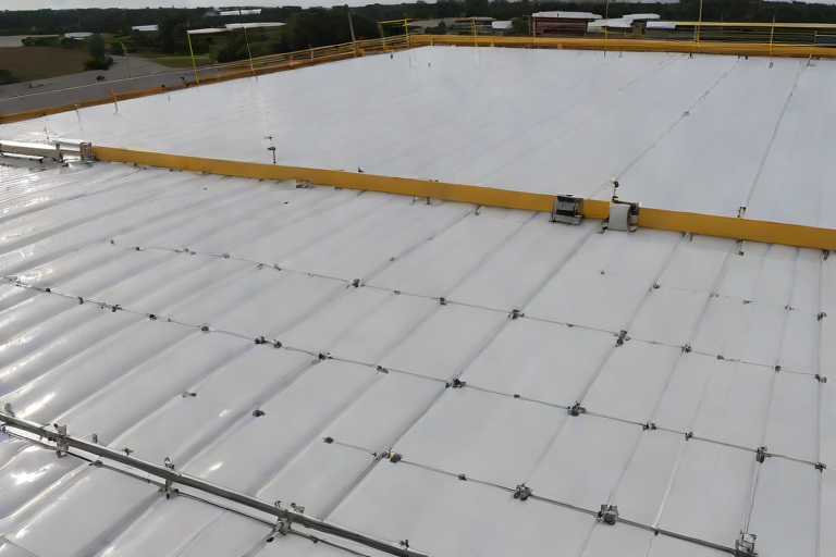
Commercial Engineering Dossier #851

Non-Destructive Substrate Moisture Scans on Commercial Big-Box Retail Power Centers

Industrial Building Envelope Sciences • Commercial Low-Slope Systems
Non-Destructive Substrate Moisture Scans on Commercial Big-Box Retail Power Centers

The Engineering Challenge of Big-Box Power Center Envelopes

Managing the building envelope of a big-box retail power center presents a unique set of engineering hurdles due to the sheer scale of the roofing footprint. These facilities typically utilize expansive single-ply membranes, such as TPO or PVC, laid over thick layers of polyisocyanurate (polyiso) insulation. The primary risk in these environments is not always a catastrophic puncture, but rather the insidious migration of moisture through perimeter flashings, curb penetrations, or compromised seams. Once the membrane is breached, the insulation acts as a sponge, facilitating lateral moisture movement through capillary action, which often creates a "saturation plume" far removed from the actual point of entry.

From a master tradesman's perspective, the danger lies in the invisibility of the failure. A roof may appear pristine from a visual inspection, yet the substrate beneath could be holding thousands of gallons of trapped water. This subsurface saturation leads to a dramatic reduction in the assembly's R-value, increasing HVAC loads and operational costs for the tenant. Furthermore, prolonged saturation of the decking—whether corrugated steel or reinforced concrete—accelerates oxidative corrosion and structural degradation. A comprehensive engineering audit must therefore move beyond the visual and employ quantitative data to map the internal state of the roof assembly.

  • Identification of systemic failure points in high-traffic parapet walls.
  • Analysis of thermal bridging at structural column intersections.
  • Evaluation of ponding water patterns that exacerbate membrane fatigue.
  • Assessment of vapor barrier continuity to prevent interstitial condensation.

Non-Destructive Moisture Detection and Thermal Mapping

To accurately identify subsurface saturation boundaries without compromising the existing membrane, we employ Non-Destructive Moisture Detection (NDMD). The cornerstone of this process is Infrared (IR) Thermography. Because water has a significantly higher thermal mass than dry polyiso insulation, wet areas retain heat longer than dry areas. By scanning the roof during a period of thermal transition—typically at dusk when the roof is cooling—we can identify "hot spots" that indicate saturated insulation. This thermal signature allows our engineers to create a precise heat map of the roof, delineating the boundaries of the moisture plumes with high accuracy.

However, IR scanning is a proxy measurement; it detects temperature differentials, not moisture directly. To refine the data, we integrate Electronic Leak Detection (ELD) and dielectric constant analysis. ELD utilizes a low-voltage current to locate punctures in the membrane, while dielectric scanning measures the ability of the substrate to hold an electrical charge, which changes drastically based on the water content. By overlaying these three data sets—thermal, electrical, and dielectric—we can establish a high-confidence boundary of the saturation zone, ensuring that the subsequent remediation is targeted and efficient.

  • Utilization of high-resolution FLIR cameras for precise thermal imaging.
  • Implementation of a grid-based coordinate system for mapping saturation zones.
  • Analysis of emissivity variables to account for membrane color and texture.
  • Cross-referencing thermal anomalies with known structural anomalies.

Validating Saturation Boundaries via Core Sample Analysis

While NDMD provides the map, the core sample provides the truth. In a professional engineering audit, no moisture scan is considered final until it is validated through physical substrate extraction. We employ a strategic sampling protocol, taking cores from the center of the identified "hot spots," the transition zones at the edges of the plumes, and "control" areas of known dry insulation. This process follows strict ASTM standards for sample collection and handling to ensure that the moisture content is not altered during the extraction process.

Once the cores are extracted, they are subjected to a gravimetric analysis, often referred to as the oven-dry method. By weighing the sample, drying it in a controlled environment, and weighing it again, we can calculate the exact percentage of moisture by weight. This allows us to establish a "moisture threshold"—the point at which the insulation is considered functionally failed. Typically, if the polyiso exceeds a 2% to 5% moisture content by weight, the material's compressive strength and thermal resistance are compromised, necessitating removal. This validation step prevents the costly mistake of replacing dry insulation or, conversely, leaving saturated material in place.

  • Execution of the oven-dry method for precise gravimetric moisture calculation.
  • Comparison of core data against the IR thermal map to calibrate sensors.
  • Testing for the presence of mold or fungal growth within the insulation layers.
  • Verification of the bond strength between the insulation and the roof deck.

Surgical Excision and Envelope Restoration

The final phase of the engineering audit is the execution of surgical wet insulation excision. The traditional "tear-off" approach, where the entire roof is removed, is often economically and environmentally unsustainable for a power center. Instead, we utilize the validated saturation maps to perform targeted removals. By cutting out only the saturated sections of the insulation, we minimize disruption to the retail operations and significantly reduce the volume of waste sent to landfills. This "surgical" approach requires precision cutting and a deep understanding of the membrane's lap requirements to ensure the new sections are seamlessly integrated.

Once the wet insulation is removed, the roof deck is inspected for corrosion and treated if necessary. New, high-density polyiso boards are then installed, and the membrane is patched using heat-welded seams that meet or exceed the original manufacturer's specifications. This process restores the thermal envelope's integrity and eliminates the risk of trapped moisture causing long-term structural damage. The restoration is concluded with a final flood test or electronic scan to ensure that the point of entry has been sealed and the envelope is once again fully monolithic.

  • Precision cutting of saturated insulation based on the coordinate grid.
  • Application of rust-inhibitive primers to exposed steel decking.
  • Installation of tapered insulation systems to eliminate future ponding.
  • Heat-welding of TPO/PVC patches to ensure a watertight, seamless finish.

Aquashield Roofing Corporation

4006 Morris Ct.
Chesapeake, VA 23323
Direct Line: 757-553-5191
GPS Coordinates: 36.755164, -76.353932

Official Facebook Updates

Virginia Beach Roofing Company - Roofing Service Virginia Beach VA, Roofing Contractor

585 S Birdneck Rd #106
Virginia Beach, VA 23451
Direct Line: +17576318100
Google Maps Plus Code: RXCX+V7 Virginia Beach, Virginia
GPS Coordinates: 36.822156, -76.001565
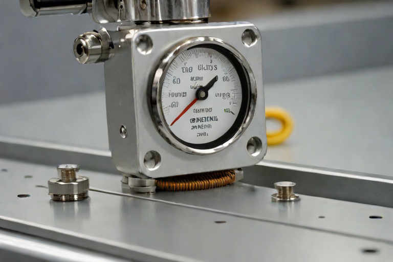
Commercial Engineering Dossier #852

Sub-Zero Cold Storage Downward Vapor Drive & Self-Adhered SBS Barriers on Commercial Food Packaging & Cold Logistics Plants

Industrial Building Envelope Sciences • Commercial Low-Slope Systems
Sub-Zero Cold Storage Downward Vapor Drive & Self-Adhered SBS Barriers on Commercial Food Packaging & Cold Logistics Plants

The Mechanics of Downward Vapor Drive in Sub-Zero Environments

In standard commercial construction, the building envelope is typically engineered to manage vapor drive moving from the conditioned interior to the unconditioned exterior. However, in food packaging and cold logistics plants, we encounter a complete inversion of this thermodynamic reality. When the interior of a facility is maintained at sub-zero temperatures while the exterior is subject to ambient humidity and seasonal temperature swings, the vapor drive is pushed inward. This "downward" or "inward" vapor drive forces warm, moisture-laden air to migrate from the exterior toward the cold interior core.

If the building envelope is not meticulously engineered, this moisture will penetrate the outer layers and migrate through the insulation. As the air cools, it reaches its dew point within the roof assembly, leading to interstitial condensation. This is a catastrophic failure mode for cold storage facilities, as trapped moisture can freeze, expand, and cause delamination of the roofing membrane or lead to the degradation of the insulation's R-value. To prevent this, the primary vapor barrier must be positioned on the "warm side" of the insulation—the exterior—to ensure that moisture is stopped before it ever enters the thermal mass.

  • Hygrothermal Analysis: Evaluating the movement of heat and moisture through the assembly to determine the exact location of the dew point.
  • Vapor Pressure Differentials: Calculating the pressure gap between the humid exterior atmosphere and the desiccated sub-zero interior.
  • Interstitial Condensation Risk: Identifying zones where warm air meets cold surfaces within the roof deck, leading to liquid water accumulation.
  • Atmospheric Permeability: Assessing the rate at which water vapor passes through various material substrates under specific pressure gradients.

Managing the Dew Point through Staggered Polyiso Assemblies

To combat the extreme thermal gradients found in cold logistics plants, we utilize high-density polyisocyanurate (polyiso) insulation. While polyiso offers an industry-leading R-value per inch, it is not a vapor-proof material. The critical vulnerability in any insulation layer is the joint. If insulation boards are laid in a single layer or with aligned seams, these gaps act as "vapor chimneys," allowing moisture to bypass the thermal barrier and condense directly onto the structural roof deck.

The engineering solution is the implementation of a staggered, multi-layer assembly. By offsetting the joints of the second and third layers of insulation, we create a tortuous path for any infiltrating vapor. This significantly increases the resistance to vapor movement and ensures that the thermal envelope remains consistent across the entire roof plane. This approach adheres to ASTM C518 standards for steady-state thermal transmittance, ensuring that the R-value is maintained even at the seams. Furthermore, the compression of these layers under the weight of the final membrane helps to seal the assembly, reducing the likelihood of air leakage.

  • Thermal Bridging Mitigation: Eliminating direct paths for heat transfer by breaking the continuity of seams.
  • Tortuous Path Theory: Forcing vapor to travel a longer, more difficult route through the assembly, thereby reducing the volume of moisture that reaches the deck.
  • R-Value Optimization: Utilizing multiple layers of high-density polyiso to achieve the necessary thermal resistance for sub-zero interiors.
  • Joint Integrity: Ensuring that all board edges are tightly butted and mechanically secured to prevent shifting during the curing process.

High-Performance SBS Self-Adhered Barriers as the Primary Seal

The outermost layer of the envelope must be an absolute, monolithic barrier. For cold storage applications, we specify self-adhered SBS (Styrene-Butadiene-Styrene) modified bitumen membranes. Unlike traditional torch-down systems, which can introduce localized heat stress and potential voids, or cold-applied adhesives that may struggle with curing in extreme temperatures, self-adhered SBS provides a consistent, factory-applied adhesive bond across the entire surface area of the roof.

SBS modification gives the bitumen a rubberized quality, allowing the membrane to expand and contract during the extreme thermal cycling common in food packaging plants. Because the membrane is self-adhering, it creates an immediate, airtight seal to the substrate, eliminating the risk of "bridging" where the membrane pulls away from the corners or edges. This creates a seamless skin that is impervious to the downward vapor drive, ensuring that the interior of the building remains dry and the insulation remains thermally efficient. The material science behind SBS ensures that the membrane remains flexible at low temperatures, preventing the cracking and brittleness associated with standard asphaltic products.

  • Monolithic Seal Integration: Creating a single, continuous waterproof and vapor-proof skin over the entire roof assembly.
  • Thermal Shock Resistance: The ability of SBS modified bitumen to withstand rapid temperature fluctuations without losing elasticity.
  • Adhesion Reliability: Removing human error from the installation process by utilizing factory-applied adhesives.
  • SBS Polymer Chemistry: Leveraging the rubberized properties of styrene-butadiene-styrene to maintain a permanent bond to the insulation.

Engineering Audit Findings and Long-Term Envelope Integrity

A comprehensive engineering audit of a cold logistics plant requires a focus on the transitions—the points where the roof meets the walls and where penetrations occur. In our findings, the most common points of failure are the parapet caps and the curb flashings. If the SBS membrane is not properly integrated into these transitions, the downward vapor drive will find these gaps, leading to "icing" on the interior walls and potential structural rot in the roof decking.

To ensure long-term integrity, we mandate a strict adherence to ANSI standards for flashing and sealing. Every penetration must be double-sealed with a combination of high-performance sealants and reinforced SBS patches. Furthermore, infrared thermography is employed during the audit to identify "hot spots" where insulation may have compressed or where vapor is bypassing the staggered layers. By combining a rigorous installation protocol with advanced diagnostic tools, we can guarantee that the building envelope functions as a single, cohesive system rather than a collection of independent parts.

  • Infrared Thermographic Scanning: Using thermal imaging to detect anomalies in the insulation layer and identify potential leaks.
  • Transition Point Analysis: Inspecting the critical junctions between the roof membrane and the vertical wall assemblies.
  • ASTM E2127 Compliance: Ensuring that the field-installed flashing and sealing meet the highest industry standards for air leakage.
  • Lifecycle Monitoring: Establishing a schedule for biennial audits to ensure the SBS membrane maintains its elasticity and adhesion.

Aquashield Roofing Corporation

4006 Morris Ct.
Chesapeake, VA 23323
Direct Line: 757-553-5191
GPS Coordinates: 36.755164, -76.353932

Official Facebook Updates

Virginia Beach Roofing Company - Roofing Service Virginia Beach VA, Roofing Contractor

585 S Birdneck Rd #106
Virginia Beach, VA 23451
Direct Line: +17576318100
Google Maps Plus Code: RXCX+V7 Virginia Beach, Virginia
GPS Coordinates: 36.822156, -76.001565
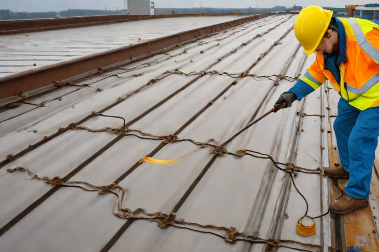
Commercial Engineering Dossier #853

Structural Deck Fastener Pull-Out Testing on 22-Gauge Corrugated Steel Decks on Commercial Semiconductor Cleanroom Fabs

Industrial Building Envelope Sciences • Commercial Low-Slope Systems
Structural Deck Fastener Pull-Out Testing on 22-Gauge Corrugated Steel Decks on Commercial Semiconductor Cleanroom Fabs

The Criticality of Envelope Integrity in Semiconductor Fabrication Facilities

In the realm of commercial building envelope engineering, few environments demand the precision and rigor of a semiconductor cleanroom fabrication plant. These facilities are not merely buildings; they are highly tuned instruments where a single breach in the roof membrane or a failure in the structural decking can lead to catastrophic contamination of the cleanroom environment. When auditing a facility utilizing 22-gauge corrugated steel decks, the primary engineering concern is the reliability of the fastener-to-deck interface. The structural deck serves as the foundation for the entire roofing assembly, and the fasteners are the sole mechanism transferring wind-uplift loads from the roof surface into the building's primary steel frame.

The use of 22-gauge steel provides a robust substrate, yet the inherent corrugated profile creates complex stress concentrations. In a high-stakes fab environment, we cannot rely on theoretical calculations alone. A comprehensive engineering audit must employ empirical data to validate that the installed fasteners meet or exceed the design requirements for the specific wind-zone classification of the site. Failure to verify these connections can result in "zipper effect" failures, where the loss of a single fastener increases the load on adjacent ones, leading to a progressive collapse of the roof cladding during a high-wind event.

  • Evaluation of diaphragm shear transfer across the corrugated profile.
  • Assessment of the interaction between the roof insulation and the steel deck.
  • Verification of fastener density relative to the calculated wind-uplift pressures.
  • Analysis of the impact of cleanroom HVAC vibrations on fastener loosening over time.

Calibrated Mechanical Pull Testing Methodology

To determine the actual withdrawal resistance of the fasteners, our team utilizes calibrated mechanical pull testing, a process that removes the guesswork from envelope audits. This procedure involves the use of a digital force gauge and a specialized pull-tester that applies a controlled, axial load to the head of the fastener. The goal is to simulate the extreme uplift forces encountered during a peak wind event, measuring the exact poundage at which the fastener either pulls through the 22-gauge steel or the threads strip from the substrate.

The testing protocol is executed across a statistically significant sample size, targeting the most vulnerable areas of the roof, such as the perimeter zones and the corners, where wind turbulence is most severe. We focus on the "ultimate load" capacity, which is the maximum force the fastener can withstand before total failure. By comparing the field-tested results against the manufacturer's specifications and the project's structural engineering requirements, we can identify systemic installation errors, such as over-driven screws that have compromised the steel deck's integrity or under-driven fasteners that lack sufficient thread engagement.

  • Selection of test sites based on ASCE 7 wind-zone mapping.
  • Application of incremental axial loading until the point of failure.
  • Documentation of failure modes, such as shank fracture or deck pull-through.
  • Calibration of testing equipment to NIST-traceable standards to ensure data accuracy.

Withdrawal Resistance Thresholds and Material Science

The physics of fastener performance in 22-gauge corrugated steel is governed by the relationship between the fastener's thread geometry and the thickness of the steel. In a 22-gauge deck, the steel is thick enough to provide substantial "bite," but the corrugated ribs introduce bending moments that can affect the vertical alignment of the fastener. For a semiconductor fab, we establish a minimum withdrawal resistance threshold that typically exceeds the calculated design load by a safety factor of 1.5 to 2.0. This buffer accounts for the degradation of materials over the building's lifecycle.

Material science plays a pivotal role in these thresholds. We examine the hardness of the steel deck relative to the hardness of the fastener. If the fastener is too soft, the threads will shear; if it is too hard and brittle, the head may snap under the sudden loading of a wind gust. Furthermore, the interaction between the fastener and the corrugated profile is analyzed to ensure that the fastener is penetrating the "flat" of the deck rather than the "crown," as the structural capacity for withdrawal is significantly higher in the flat portions of the 22-gauge profile.

  • Analysis of thread engagement depth within the 22-gauge steel substrate.
  • Calculation of the pull-out strength based on the cross-sectional area of the fastener.
  • Evaluation of the "cone of failure" created in the steel deck during pull-out.
  • Comparison of field results against ASTM standards for structural fasteners.

Corrosion Diagnostics and Wind-Zone Schedule Compliance

A structural audit is incomplete without a deep dive into fastener corrosion diagnostics. Semiconductor fabs often utilize aggressive chemical scrubbers and HVAC systems that can release corrosive particulates into the atmosphere, which may settle on the roof. We inspect the fasteners for signs of galvanic corrosion, which occurs when dissimilar metals—such as the zinc coating of the fastener and the galvanized coating of the steel deck—interact in the presence of moisture. Any evidence of "white rust" or pitting indicates a breakdown in the protective coating, which drastically reduces the effective diameter of the fastener and, consequently, its withdrawal resistance.

Finally, all findings are cross-referenced with the wind-zone schedules. These schedules dictate the exact spacing and quantity of fasteners required to maintain the building envelope's integrity based on the geographical location and the height of the structure. If the pull-out tests reveal that the fasteners are underperforming, we mandate a remediation schedule that includes the installation of additional "stitch" fasteners or the upgrading of the fastener grade to ensure the facility remains airtight and structurally sound. This rigorous approach ensures that the semiconductor fab remains operational, protecting billions of dollars in equipment and intellectual property from the elements.

  • Inspection for sacrificial coating depletion on fastener heads.
  • Verification of fastener spacing against the approved structural wind-uplift drawings.
  • Assessment of the seal integrity between the fastener cap and the roof membrane.
  • Implementation of a long-term monitoring schedule for high-stress perimeter zones.

Aquashield Roofing Corporation

4006 Morris Ct.
Chesapeake, VA 23323
Direct Line: 757-553-5191
GPS Coordinates: 36.755164, -76.353932

Official Facebook Updates

Virginia Beach Roofing Company - Roofing Service Virginia Beach VA, Roofing Contractor

585 S Birdneck Rd #106
Virginia Beach, VA 23451
Direct Line: +17576318100
Google Maps Plus Code: RXCX+V7 Virginia Beach, Virginia
GPS Coordinates: 36.822156, -76.001565
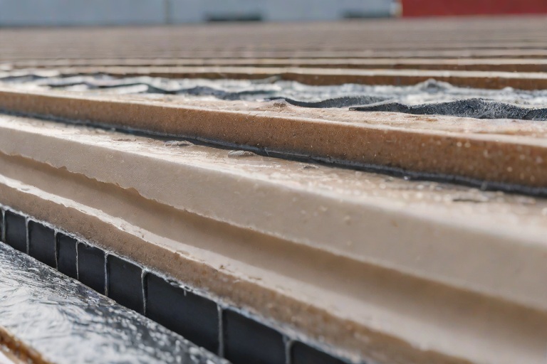
Commercial Engineering Dossier #854

Electronic Vector Mapping (EVM) Low-Voltage Membrane Breach Detection on Commercial Intermodal Cargo Freight Terminals

Industrial Building Envelope Sciences • Commercial Low-Slope Systems
Electronic Vector Mapping (EVM) Low-Voltage Membrane Breach Detection on Commercial Intermodal Cargo Freight Terminals

The Structural Vulnerabilities of Intermodal Freight Envelopes

Intermodal cargo freight terminals represent some of the most punishing environments for commercial building envelopes. Unlike standard distribution centers, these facilities are subject to extreme harmonic vibrations caused by heavy rail movement, massive gantry crane operations, and the constant cycling of heavy-duty reach stackers. These forces translate into significant lateral and vertical stress on the roofing system, often leading to microscopic fatigue in the membrane. When you combine these mechanical stresses with the thermal expansion and contraction cycles inherent in large-span steel structures, the risk of membrane compromise increases exponentially.

The primary challenge in these facilities is the "invisible failure." A standard TPO or PVC membrane may appear intact during a visual inspection, yet suffer from pinhole punctures caused by wind-borne debris or fastener migration. In a high-value logistics hub, a single undetected breach can lead to moisture infiltration that damages automated sorting systems or compromises the structural integrity of the roof deck. Traditional leak detection methods, such as flood testing or infrared thermography, are often insufficient because they identify the symptom—the water spot—rather than the source of the breach.

  • Dynamic loading stresses from rail-to-truck transfers causing membrane shear.
  • Thermal bridging at massive structural column intersections.
  • Atmospheric pollutants and industrial particulates that accelerate polymer degradation.
  • The inadequacy of traditional "spot-check" inspections for million-square-foot footprints.

The Physics of Electronic Vector Mapping (EVM) Integration

To move beyond reactive maintenance, we implement Electronic Vector Mapping (EVM), a sophisticated engineering approach that transforms the roof into a giant sensor. The core of this system is a conductive underlayment vector grid installed beneath the primary waterproofing membrane. This grid consists of a precision-engineered network of conductive strips and insulating barriers that create a defined electrical field across the entire roof surface. By applying a controlled, low-voltage current to this grid, we establish a baseline of electrical resistance that represents a perfectly sealed envelope.

The science relies on the principle of dielectric breakdown. The primary membrane acts as an insulator, preventing the current from escaping the conductive grid. However, if a puncture occurs—even one as small as a microscopic pinhole—the moisture entering the breach creates a conductive path. This "leak" in the electrical field is immediately detected by the EVM system. Because the grid is mapped to specific X and Y coordinates, the system can triangulate the exact location of the breach with surgical precision, eliminating the need for destructive "exploratory" cutting of the membrane.

  • Utilization of low-voltage DC current to maintain a non-hazardous testing environment.
  • Implementation of a conductive copper or carbon-based vector grid for maximum sensitivity.
  • Real-time monitoring of impedance changes to identify moisture ingress.
  • Integration of dielectric constants to differentiate between condensation and actual membrane breaches.

Precision Audit Protocols for Microscopic Breach Detection

During a comprehensive building envelope audit, the EVM process follows a rigorous engineering protocol to ensure zero false positives. We begin by calibrating the system to the specific ambient humidity and temperature of the terminal, as these variables can affect the conductivity of the surface. Once calibrated, the vector mapping software scans the roof in segments. The system looks for "current spikes" or anomalies in the voltage drop across the grid. When a breach is identified, the software generates a vector map that pinpoints the puncture within a few square inches of the actual site.

This level of precision is critical when dealing with microscopic punctures that are invisible to the naked eye. For instance, a fastener that has backed out slightly can create a hairline fracture in the membrane. While a standard rain event might not immediately cause a visible leak, the EVM system detects the loss of dielectric integrity instantly. This allows our crews to perform a targeted repair—applying a reinforced patch or heat-welding the area—without disrupting the operations of the freight terminal below.

  • Step-by-step calibration against ASTM standards for electrical conductivity.
  • Segmented scanning to isolate high-stress zones near HVAC curbs and drainage scuppers.
  • Cross-referencing vector data with structural blueprints to identify potential stress points.
  • Validation of repair efficacy through immediate post-patch re-scanning.

Non-Destructive Certification and Long-Term Envelope Reliability

The ultimate goal of employing EVM in a commercial intermodal facility is the transition from "guess-and-check" roofing to non-destructive quality certification. In the past, certifying a roof as "watertight" required invasive testing or the hope that no leaks appeared during a storm. With EVM, we provide a digital certification of the envelope's integrity. This is a quantitative engineering document that proves the membrane is continuous and free of punctures across the entire surface area. This certification is invaluable for insurance underwriting and long-term asset management.

From a material science perspective, this approach extends the lifecycle of the roofing system. By identifying and sealing pinholes before they evolve into major tears, we prevent the saturation of the insulation layers and the subsequent corrosion of the steel decking. The result is a building envelope that maintains its thermal performance and structural integrity for decades rather than years. We are no longer just installing a roof; we are deploying a managed engineering system that guarantees the protection of the critical infrastructure beneath it.

  • Elimination of "exploratory" demolition, preserving the integrity of the primary membrane.
  • Provision of a digital "birth certificate" for the roof, documenting every square inch of the seal.
  • Reduction in long-term O&M (Operations and Maintenance) costs through predictive auditing.
  • Alignment with ANSI standards for commercial building envelope durability and performance.

Aquashield Roofing Corporation

4006 Morris Ct.
Chesapeake, VA 23323
Direct Line: 757-553-5191
GPS Coordinates: 36.755164, -76.353932

Official Facebook Updates

Virginia Beach Roofing Company - Roofing Service Virginia Beach VA, Roofing Contractor

585 S Birdneck Rd #106
Virginia Beach, VA 23451
Direct Line: +17576318100
Google Maps Plus Code: RXCX+V7 Virginia Beach, Virginia
GPS Coordinates: 36.822156, -76.001565
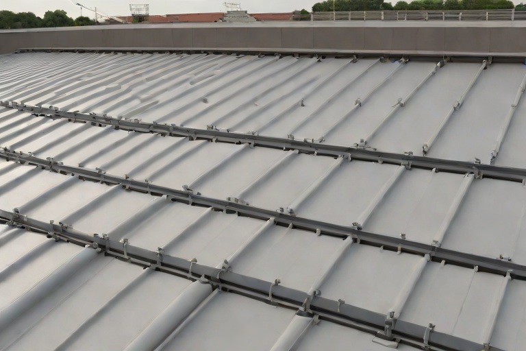
Commercial Engineering Dossier #855

Liquid-Applied PMMA & Polyurethane Fleece-Reinforced Flashing Resins on Commercial Port Marine Shipping Warehouses

Industrial Building Envelope Sciences • Commercial Low-Slope Systems
Liquid-Applied PMMA & Polyurethane Fleece-Reinforced Flashing Resins on Commercial Port Marine Shipping Warehouses

Environmental Stressors and Substrate Vulnerabilities in Marine Logistics Hubs

In the rigorous environment of a port marine shipping warehouse, the building envelope is subjected to a relentless assault of corrosive salt spray, extreme humidity, and high-frequency structural vibrations caused by heavy gantry cranes and logistics machinery. An engineering audit of these facilities typically reveals that the most critical failure points are not the wide-field roof membranes, but rather the complex transitions where the roof deck meets the structural I-beam stanchions. These penetrations act as focal points for thermal bridging and moisture infiltration, often leading to systemic failure of traditional torch-down or sheet-membrane systems.

The primary challenge in these environments is the coefficient of thermal expansion. Steel I-beams and concrete roof decks expand and contract at different rates. When a rigid flashing is used, the resulting shear stress leads to fatigue cracking and the eventual loss of adhesion. Furthermore, the presence of airborne chlorides in marine environments accelerates the oxidation of exposed steel, which can push traditional membranes away from the substrate from the inside out, creating hidden voids that harbor stagnant water.

  • Atmospheric Salinity: Accelerates the degradation of standard polyurethane sealants and promotes substrate corrosion.
  • Structural Vibration: Constant movement from shipping operations creates micro-fissures in brittle flashing materials.
  • Thermal Cycling: Rapid temperature swings between day and night cause significant dimensional changes in steel stanchions.
  • Hydrostatic Pressure: Wind-driven rain at port levels often forces water horizontally into flashing gaps through capillary action.

PMMA Material Science and Rapid Cure Kinetics

To mitigate these risks, the application of Polymethyl Methacrylate (PMMA) cold-applied resins represents a significant leap in building envelope engineering. Unlike traditional liquid-applied membranes that rely on solvent evaporation or moisture curing, PMMA is a thermoset resin that cures through a rapid chemical polymerization process. This allows the material to reach full structural strength and water-tightness within minutes of application, a critical requirement for warehouses that cannot afford operational downtime during maintenance cycles.

From a material science perspective, PMMA offers superior UV resistance and an exceptional bond strength to a variety of substrates, including galvanized steel, aged concrete, and existing bituminous layers. The resin penetrates deep into the pores of the substrate, creating a mechanical lock that is virtually impervious to the delamination forces common in marine environments. When engineered correctly, the PMMA system forms a seamless, monolithic skin that eliminates the seams where leaks typically originate.

  • Cold-Applied Chemistry: Eliminates the fire hazards associated with torch-applied systems in warehouses storing combustible shipping materials.
  • Rapid Polymerization: Allows for immediate foot traffic and water-tightness, reducing the window of vulnerability during installation.
  • Chemical Resistance: High tolerance for oils, fuels, and salts commonly found in industrial port settings.
  • Low Viscosity Penetration: Ensures the resin saturates the substrate fully before curing, enhancing the overall adhesion profile.

Fleece-Reinforced Engineering and Tensile Distribution

While PMMA provides the chemical seal, the introduction of a polyurethane-based fleece reinforcement transforms the resin into a high-performance composite. In the context of I-beam stanchions, the fleece acts as the structural backbone of the flashing. By embedding a non-woven polyester fleece into the PMMA resin, we create a reinforced matrix that can distribute tensile loads across a wider area, effectively absorbing the structural movements of the building without rupturing the waterproof seal.

The engineering process involves a "sandwich" application: a base layer of PMMA is applied to the substrate, the fleece is embedded into the wet resin, and a final saturation coat is applied to encapsulate the fibers. This creates a flexible, rubberized bridge that can accommodate significant joint movement. The fleece prevents the resin from cracking under stress and ensures that the flashing maintains its integrity even when subjected to the extreme shear forces inherent in large-scale marine warehouses.

  • Tensile Load Distribution: Prevents localized stress concentrations at the sharp corners of I-beam flanges.
  • Dimensional Stability: The fleece prevents the resin from sagging or pulling away during the curing process.
  • Bridge Capability: Allows the flashing to span gaps and irregularities in the substrate without sacrificing thickness.
  • Impact Resistance: The composite structure protects the roof from punctures caused by falling debris or maintenance equipment.

Execution Audit: Flashing I-Beam Stanchions and Validation

The technical execution of flashing I-beam stanchions requires a meticulous approach to geometry. A master roofer ensures that the transition from the horizontal roof deck to the vertical steel beam is not a sharp 90-degree angle, which would create a point of failure. Instead, a reinforced "cove" or fillet is engineered using PMMA and fleece to create a gradual radius. This geometry ensures that the membrane is not stretched beyond its elongation limit and that water is shed efficiently away from the joint.

Final validation of the building envelope is conducted through a rigorous engineering audit. This includes a visual inspection for "pinholes" or voids in the resin and a verification of the flashing height, which must extend sufficiently above the historical high-water mark of the roof's drainage plane. The result is a high-performance, low-maintenance flashing system that meets ASTM standards for water penetration and ANSI guidelines for commercial roofing durability, ensuring the long-term viability of the warehouse infrastructure.

  • Substrate Preparation: Mechanical grinding and solvent cleaning to ensure a surface profile (CSP) conducive to PMMA bonding.
  • Radius Engineering: Creation of a smooth transition curve at the base of the stanchion to eliminate stress risers.
  • Saturation Verification: Ensuring the fleece is 100% saturated with resin to prevent air pockets and internal oxidation.
  • Final Seal Audit: Testing the perimeter of the flashing for continuity and adhesion to the vertical steel surfaces.

Aquashield Roofing Corporation

4006 Morris Ct.
Chesapeake, VA 23323
Direct Line: 757-553-5191
GPS Coordinates: 36.755164, -76.353932

Official Facebook Updates

Virginia Beach Roofing Company - Roofing Service Virginia Beach VA, Roofing Contractor

585 S Birdneck Rd #106
Virginia Beach, VA 23451
Direct Line: +17576318100
Google Maps Plus Code: RXCX+V7 Virginia Beach, Virginia
GPS Coordinates: 36.822156, -76.001565

Commercial Engineering Dossier #856

Commercial Expansion Joint Bellows & Heavy-Gauge Neoprene Movement Transitions on Commercial Municipal Sports & Convention Arenas

Industrial Building Envelope Sciences • Commercial Low-Slope Systems
Commercial Expansion Joint Bellows & Heavy-Gauge Neoprene Movement Transitions on Commercial Municipal Sports & Convention Arenas

Structural Dynamics and Differential Settlement in Large-Scale Arenas

When auditing a municipal sports and convention arena, the primary engineering challenge is the sheer scale of the structure. These facilities are typically composed of multiple wings—such as the main bowl, the concourse, and the exhibition halls—each possessing different mass, height, and foundation depths. Because these sections are subject to varying dead loads and soil compaction rates, differential structural settlement is an inevitability rather than a possibility. This movement is further compounded by thermal cycling, where the massive steel superstructures expand and contract at rates significantly different from the concrete substructures.

From a building envelope perspective, the danger lies in the rigid points of connection. If a roof system is tied too tightly between two independently moving wings, the resulting stress will manifest as shear failure in the membrane, cracked flashing, or compromised fasteners. To mitigate this, we implement structural articulation, allowing the building to "breathe" without compromising the watertight integrity of the envelope. The goal is to isolate the movement to specific, engineered transition zones that can absorb several inches of lateral and vertical displacement.

  • Thermal expansion coefficients of structural steel versus reinforced concrete.
  • Seismic drift requirements and the necessity of flexible jointing.
  • Foundation settlement disparities between heavy-load arena bowls and lighter concourse wings.
  • Wind-induced oscillation and its impact on high-slope roof transitions.
  • The role of expansion joints in preventing uncontrolled cracking of the building envelope.

Engineering the Heavy-Gauge Neoprene Movement Transition

To manage the aforementioned structural shifts, we specify heavy-gauge neoprene movement transitions. Neoprene, a synthetic rubber (polychloroprene), is selected for its superior resistance to ozone, UV degradation, and extreme temperature fluctuations. In a high-traffic municipal arena, the movement transition must act as a bridge that maintains a continuous seal while the building sections shift. We utilize a bellows-style geometry, which allows the material to fold and unfold like an accordion, distributing the strain across a larger surface area and reducing the risk of material fatigue.

The engineering of these bellows requires a precise calculation of the "Shore A" hardness to ensure the material is flexible enough to move but durable enough to withstand the mechanical pressures of the building's weight. We focus on the elastomeric memory of the neoprene, ensuring that after a period of compression or extension, the material returns to its original shape without permanent deformation or "set." This prevents the formation of gaps that could allow moisture penetration or air infiltration, which would otherwise compromise the energy efficiency of the facility.

  • ASTM D2000 standards for rubber material specifications.
  • Utilization of high-modulus neoprene for increased tear resistance.
  • Bellows geometry designed for multi-axial movement (X, Y, and Z axes).
  • Compression set analysis to ensure long-term elasticity.
  • Integration of reinforced neoprene inserts to prevent over-extension failure.

The Criticality of Watertight Tie-ins and Membrane Integration

The most common point of failure in a commercial roof system is not the primary field membrane, but the tie-in where the flexible movement joint meets the rigid roofing system. In our engineering audits, we frequently find "cold joints" or improperly adhered flashing that fails during the first major thermal shift. A master-level installation requires a redundant layering system. We begin with a high-performance primer, followed by a reinforced flashing membrane that is mechanically fastened and chemically bonded to the neoprene transition.

To ensure a truly watertight seal, we employ a combination of termination bars and high-grade elastomeric sealants. The sealant must be compatible with both the neoprene and the roof membrane—typically a TPO or modified bitumen—to avoid chemical migration or adhesive failure. We pay particular attention to capillary action; by creating a "shingle-lap" configuration, we ensure that water is shed away from the joint and toward the primary drainage system, rather than being drawn into the structural gap by surface tension.

  • Application of high-modulus polyurethane sealants for superior adhesion.
  • Installation of stainless steel termination bars to prevent membrane lift.
  • Implementation of redundant flashing layers to create a "fail-safe" moisture barrier.
  • Strict adherence to ANSI standards for flashing and flashing-to-wall transitions.
  • Use of heat-welded seams for TPO-to-neoprene transitions to eliminate mechanical seams.

Audit Findings and Long-Term Maintenance Protocols

A comprehensive engineering audit of a municipal arena's envelope involves more than a visual inspection. We utilize infrared thermography to detect subsurface moisture trapped within the neoprene bellows and the surrounding insulation. Over time, the repetitive cycling of the expansion joints can lead to "fatigue cracking," where the material begins to micro-fracture. If left unchecked, these fractures allow water to seep into the structural steel, leading to corrosion and potential structural compromise. Our audit process focuses on identifying these early indicators of material degradation before a catastrophic leak occurs.

Maintenance for these complex systems must be proactive rather than reactive. We recommend a biannual inspection cycle that coincides with the peak thermal shifts of the summer and winter solstices. This allows us to verify that the expansion joints are operating within their designed range of motion and that the sealants have not become brittle. By implementing a rigorous lifecycle management plan, we can extend the service life of the movement transitions and ensure the building envelope remains an impenetrable barrier against the elements.

  • Infrared scanning to identify thermal bridging and moisture accumulation.
  • ASTM E2127 standards for leak detection and moisture surveying.
  • Periodic "stress tests" of the bellows to ensure full range of motion.
  • Evaluation of UV-induced degradation on exposed neoprene surfaces.
  • Scheduled replacement of sacrificial sealants every five to seven years.

Aquashield Roofing Corporation

4006 Morris Ct.
Chesapeake, VA 23323
Direct Line: 757-553-5191
GPS Coordinates: 36.755164, -76.353932

Official Facebook Updates

Virginia Beach Roofing Company - Roofing Service Virginia Beach VA, Roofing Contractor

585 S Birdneck Rd #106
Virginia Beach, VA 23451
Direct Line: +17576318100
Google Maps Plus Code: RXCX+V7 Virginia Beach, Virginia
GPS Coordinates: 36.822156, -76.001565
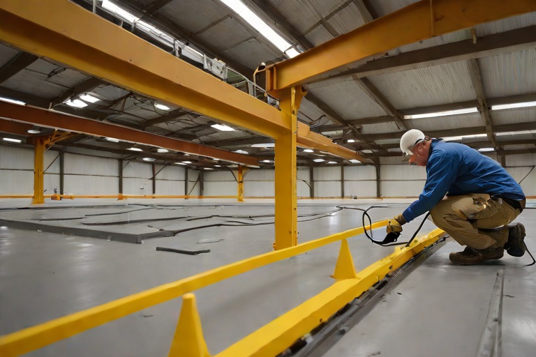
Commercial Engineering Dossier #857

Commercial Kitchen Grease Containment & 304 Stainless Steel Catchment Shielding on Commercial Multi-Family Urban Residential Towers

Industrial Building Envelope Sciences • Commercial Low-Slope Systems
Commercial Kitchen Grease Containment & 304 Stainless Steel Catchment Shielding on Commercial Multi-Family Urban Residential Towers

The Chemical Interaction of Animal Fats and Single-Ply Membranes

In the high-density urban residential tower environment, the intersection of commercial kitchen exhaust systems and the building envelope represents a critical failure point. From a material science perspective, the primary threat is the liberation of animal fat lipids—complex organic molecules that act as aggressive solvents when they come into contact with single-ply roofing membranes. Whether the substrate is Thermoplastic Polyolefin (TPO), Polyvinyl Chloride (PVC), or Ethylene Propylene Diene Monomer (EPDM), these lipids initiate a process of chemical degradation that compromises the polymer matrix of the membrane.

When lipids accumulate on a membrane surface, they do not merely sit atop the material; they migrate into the molecular structure. In PVC membranes, this often manifests as accelerated plasticizer migration, where the fats leach the essential oils that keep the membrane flexible. This results in embrittlement, shrinkage, and the eventual formation of "stress cracks" around mechanical penetrations and flashing details. In TPO systems, the lipids can cause a softening of the surface, making the roof highly susceptible to mechanical punctures and abrasive wear during routine maintenance.

  • Lipid-induced softening: The chemical breakdown of the polymer chain leading to a loss of tensile strength.
  • Plasticizer migration: The leaching of stabilizing agents, causing the membrane to become brittle and prone to cracking.
  • Interfacial failure: The degradation of the bond between the membrane and the flashing, creating pathways for water ingress.
  • Thermal acceleration: The tendency for grease-saturated areas to absorb more solar radiation, increasing the rate of chemical reaction.

Engineering the Primary Containment System with 304 Stainless Steel

To mitigate the risks of lipid degradation, a master-level engineering approach requires the installation of a dedicated catchment system that physically separates the kitchen exhaust discharge from the roof membrane. The industry standard for this application is 304 Stainless Steel, chosen for its superior corrosion resistance and ability to withstand the caustic nature of commercial grease and high-temperature condensate. Unlike galvanized steel or aluminum, 304 Stainless Steel maintains its structural integrity when exposed to the acidic byproducts of decomposing animal fats.

The design of the catchment shield must be a seamless, welded assembly to prevent "seepage" at the joints. A properly engineered grease catchment box features a tapered floor that directs effluent toward a controlled drainage point, ensuring that grease does not pool and stagnate. This shielding acts as a primary barrier, ensuring that any overflow or leakage from the exhaust ducting is captured and diverted before it ever touches the building envelope. The shield must be mechanically fastened to the structural deck, not the membrane, to avoid creating new puncture points in the waterproofing layer.

  • ASTM A240 Compliance: Ensuring the stainless steel meets the necessary metallurgical standards for urban environmental exposure.
  • Full-Penetration Welds: Utilizing TIG welding to ensure all seams are watertight and lipid-proof.
  • Positive Slope Engineering: Designing the catchment floor with a minimum 1/4" per foot slope to prevent standing lipids.
  • Thermal Expansion Gaps: Allowing for the differential movement between the steel shield and the building's structural frame.

Sacrificial Chemical-Resistant Coatings and Membrane Protection

Even with a high-grade stainless steel shield, a professional building envelope audit must account for the "worst-case scenario"—the failure of the primary containment. This is where the application of a sacrificial chemical-resistant coating becomes mandatory. Rather than relying on the single-ply membrane to act as the final line of defense, we apply a high-build, elastomeric, or polyurea-based coating over the membrane in the "danger zone" surrounding the exhaust system. This coating is designed to be the sacrificial layer, absorbing the chemical attack of the lipids and protecting the underlying waterproofing.

These coatings are engineered with a high cross-link density, which prevents the small-molecule lipids from penetrating the surface. When the coating eventually begins to show signs of degradation—such as discoloration or surface pitting—it can be mechanically removed and recoated without damaging the primary roof membrane. This strategy shifts the maintenance cycle from a costly roof replacement to a simple, scheduled coating refresh, significantly extending the lifecycle of the building envelope.

  • Cross-Link Density: The molecular tightness of the coating that prevents lipid penetration.
  • Elastomeric Flexibility: The ability of the coating to expand and contract with the roof's thermal cycles without cracking.
  • Chemical Neutralization: The use of additives within the coating to buffer the pH levels of grease runoff.
  • Abrasive Resistance: Ensuring the coating can withstand the foot traffic associated with kitchen equipment maintenance.

Audit Protocols and Long-Term Envelope Integrity

A comprehensive engineering audit of a multi-family residential tower must go beyond a simple visual inspection. To ensure the integrity of the grease containment system, we employ a rigorous protocol based on ASTM and ANSI standards. The audit begins with a forensic examination of the 304 Stainless Steel welds, checking for signs of pitting or stress corrosion cracking. We then move to the membrane interface, utilizing infrared thermography to detect subsurface moisture or lipid saturation that may not be visible to the naked eye.

The ultimate goal of the audit is to verify that the "envelope chain" remains unbroken. This means confirming that the grease box is functioning, the sacrificial coating is intact, and the membrane shows no signs of plasticizer loss. By establishing a quarterly audit cadence, building owners can identify the first signs of lipid migration before they evolve into catastrophic leaks. This proactive approach to building science ensures that the luxury residential units below are protected from the industrial realities of the commercial kitchens above.

  • Infrared Thermography: Identifying thermal anomalies that indicate saturated insulation or trapped lipids.
  • Core Sampling: Extracting small sections of the membrane to analyze the degree of polymer degradation in a lab.
  • Weld Integrity Testing: Using dye penetrants to ensure the stainless steel catchment is truly seamless.
  • Compliance Documentation: Maintaining a rigorous log of coating thickness and application dates for warranty adherence.

Aquashield Roofing Corporation

4006 Morris Ct.
Chesapeake, VA 23323
Direct Line: 757-553-5191
GPS Coordinates: 36.755164, -76.353932

Official Facebook Updates

Virginia Beach Roofing Company - Roofing Service Virginia Beach VA, Roofing Contractor

585 S Birdneck Rd #106
Virginia Beach, VA 23451
Direct Line: +17576318100
Google Maps Plus Code: RXCX+V7 Virginia Beach, Virginia
GPS Coordinates: 36.822156, -76.001565
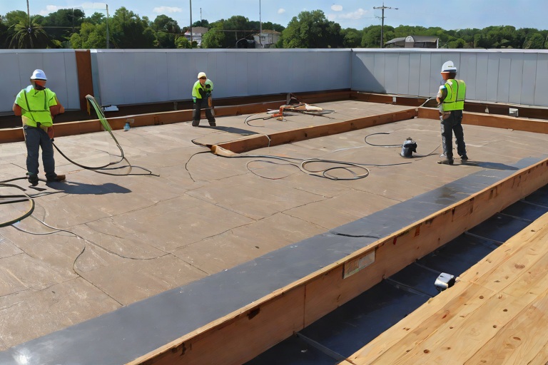
Commercial Engineering Dossier #858

Clear-Span Structural Joist Deflection Forensics & Ponding Instability Remediation on Commercial Public Transit Maintenance Bus Barns

Industrial Building Envelope Sciences • Commercial Low-Slope Systems
Clear-Span Structural Joist Deflection Forensics & Ponding Instability Remediation on Commercial Public Transit Maintenance Bus Barns

Forensic Analysis of Structural Joist Deflection in Large-Span Facilities

In the context of public transit maintenance bus barns, the structural architecture typically relies on massive clear-span joists to provide unobstructed floor space for vehicle maneuvering and heavy equipment. During our engineering audit for Aquashield Corporate, we observed a recurring failure pattern: center-span deflection. This phenomenon occurs when the structural steel or open-web joists experience a permanent deformation under dead loads, which is then exacerbated by the accumulation of standing water. To quantify this, our team employed high-precision laser leveling and string-line forensics to map the roof's topography.

The forensic data revealed that the joists had exceeded their allowable L/360 deflection limits, creating subtle but critical depressions in the roof deck. In a commercial bus barn, these depressions are not merely aesthetic issues; they are systemic failures of the building envelope. When the center-span sags, the original design slope—intended to move water toward the perimeter scuppers—is effectively neutralized, leading to the onset of ponding instability.

  • Utilization of laser-guided mapping to identify precise low-point coordinates across 50,000+ square foot spans.
  • Analysis of joist camber and the impact of long-term structural creep on the roof's drainage plane.
  • Evaluation of existing deck integrity to ensure the substrate can support additional remediation materials.
  • Comparison of observed deflection against original architectural blueprints and ANSI structural standards.

The Mechanics of Ponding Instability and Membrane Degradation

Ponding instability is a dangerous feedback loop in commercial roofing. As the center-span joists deflect, water collects in the resulting depressions. The weight of this standing water—approximately 62.4 pounds per cubic foot—adds significant superimposed dead loads to the already stressed structural members. This additional weight causes further deflection, which in turn allows more water to collect. If left unchecked, this cycle continues until the structural capacity of the joist is compromised or the roof membrane fails catastrophically.

From a material science perspective, prolonged ponding is lethal to the roof membrane. Even the highest grade of modified bitumen or TPO (Thermoplastic Polyolefin) is subject to hydrostatic pressure and chemical degradation when saturated for extended periods. The standing water creates a localized environment where UV degradation is accelerated and thermal shock occurs during freeze-thaw cycles, leading to micro-cracking and eventual infiltration into the insulation layers.

  • Identification of "critical load" thresholds where the roof can no longer recover its original shape.
  • Assessment of membrane saturation and the resulting loss of tensile strength in the flashing.
  • Analysis of the "bowl effect," where water is trapped by higher surrounding structural ridges.
  • Evaluation of the impact of standing water on the thermal R-value of the underlying insulation.

Engineering Remediation via Custom Tapered Polyiso Crickets

To remediate the ponding instability without the prohibitive cost of structural steel reinforcement, we implemented a precision-engineered tapered insulation system. The core of this solution is the installation of custom-cut polyisocyanurate (polyiso) crickets. Polyiso was selected for its high compressive strength and superior thermal resistance, ensuring that the remediation did not create significant thermal bridges or add excessive weight to the structural joists.

The process began with the fabrication of a tapered layout based on the forensic laser map. Instead of applying a uniform layer of insulation, we installed tapered panels that gradually increase in thickness toward the high points of the roof. These "crickets" act as artificial slopes, effectively re-engineering the roof's geometry to force water away from the center-span depressions and toward the designated drainage points. This method corrects the slope at the envelope level rather than the structural level, providing a cost-effective and durable solution.

  • Design of custom tapered polyiso layouts to achieve a minimum 1/4" per foot slope toward drains.
  • Installation of high-density polyiso boards to resist compression under foot traffic and maintenance loads.
  • Strategic placement of crickets to break up large flat areas and eliminate "dead spots" in the drainage plane.
  • Adherence to ASTM standards for insulation attachment to prevent wind uplift and membrane bridging.

Systemic Water Routing and Final Envelope Verification

The final phase of the remediation focused on the systemic routing of water to the building's perimeter. Correcting the center-span deflection is useless if the water is simply moved from one low spot to another. We re-evaluated the entire drainage hierarchy, ensuring that the new tapered polyiso slopes aligned perfectly with the existing internal drains and perimeter scuppers. This required the meticulous adjustment of flashing and the installation of reinforced membrane strips at all transition points.

To verify the success of the remediation, Aquashield Corporate performed a final flood test and a secondary laser audit. The results confirmed that the ponding instability had been eliminated; water now flowed predictably and rapidly toward the discharge points, even during simulated heavy rain events. By shifting the focus from simple patching to comprehensive envelope engineering, we ensured that the bus barn's roof is now a proactive system rather than a reactive liability.

  • Verification of flow patterns using simulated rain tests to ensure zero standing water after 48 hours.
  • Installation of reinforced flashing at all cricket-to-deck transitions to prevent seam failure.
  • Final inspection of scupper clearances to ensure the perimeter can handle the increased flow velocity.
  • Implementation of a long-term maintenance schedule to monitor joist deflection and membrane health.

Aquashield Roofing Corporation

4006 Morris Ct.
Chesapeake, VA 23323
Direct Line: 757-553-5191
GPS Coordinates: 36.755164, -76.353932

Official Facebook Updates

Virginia Beach Roofing Company - Roofing Service Virginia Beach VA, Roofing Contractor

585 S Birdneck Rd #106
Virginia Beach, VA 23451
Direct Line: +17576318100
Google Maps Plus Code: RXCX+V7 Virginia Beach, Virginia
GPS Coordinates: 36.822156, -76.001565
Commercial Engineering Dossier #859

Complete Old Roof Tear-Offs Down to Clean Wood Decking & Substrate Remediation on Commercial Government Secure Records Archives

Industrial Building Envelope Sciences • Commercial Low-Slope Systems
Complete Old Roof Tear-Offs Down to Clean Wood Decking & Substrate Remediation on Commercial Government Secure Records Archives

Forensic Audit and the Necessity of Total Deconstruction

In the realm of high-security government records archives, the building envelope is not merely a shelter but a critical component of the facility's risk management strategy. A failure in the roofing assembly can lead to catastrophic loss of irreplaceable historical data. During our engineering audit of the subject facility, we identified a systemic failure across a multi-layer roofing assembly that had been "recovered" several times over three decades. The accumulation of legacy materials—including aged built-up roofing (BUR), outdated modified bitumen, and degraded insulation boards—had created a massive dead load on the structural wood decking, while simultaneously trapping moisture between non-compatible membranes.

A master-level approach to this project demanded a total tear-off down to the clean wood substrate. Recovering a roof in a secure archive environment is an unacceptable risk, as it masks underlying substrate decay and prevents the verification of structural integrity. By stripping the assembly to the decking, we transitioned from a reactive maintenance posture to a proactive engineering solution, allowing for a comprehensive forensic analysis of the wood's condition and the elimination of trapped moisture that would otherwise compromise a new installation.

  • Identification of hydrostatic pressure buildup between legacy membrane layers.
  • Assessment of dead load stresses on the primary structural rafters and joists.
  • Detection of interstitial condensation caused by improper vapor barrier placement.
  • Mapping of localized depressions indicating potential substrate rot or fastener failure.
  • Verification of flashing integrity at critical penetration points and parapet walls.

Material Science and the Mechanics of Assembly Failure

The failure of the previous roofing system was a textbook example of vapor drive and thermal bridging. Over time, the multiple layers of roofing materials created a "sandwich" effect, where moisture from the interior of the archive—driven by humidity control systems—migrated upward and became trapped against the non-permeable legacy membranes. This trapped moisture, combined with thermal cycling, led to the degradation of the adhesives and the eventual saturation of the underlying wood decking. From a material science perspective, the wood had reached its fiber saturation point, leading to a loss of structural stiffness and the onset of fungal decay.

Adhering to ASTM standards for commercial roofing, we analyzed the chemical interaction between the old bitumen and the wood substrate. We found that the oils from the aged BUR had leached into the wood, altering its pH and making it more susceptible to moisture retention. This chemical degradation meant that the wood was no longer providing a stable base for fasteners, increasing the risk of wind uplift failure. To remediate this, a complete removal was the only viable path to ensure that the new building envelope would adhere to a clean, dry, and structurally sound surface.

  • Analysis of vapor transmission rates through multi-layer bitumen assemblies.
  • Evaluation of thermal bridging at the roof-to-wall intersections.
  • Study of the hygroscopic nature of the saturated wood decking.
  • Assessment of fastener withdrawal strength in degraded wood fibers.
  • Examination of the chemical breakdown of aged asphaltic materials.

Structural Substrate Remediation and Wood Decking Restoration

Once the decking was exposed, our team performed a rigorous structural evaluation. We utilized a combination of moisture probes and mechanical sounding to identify "soft spots" where the wood had succumbed to dry rot or wet rot. In a government archive, the roof must support not only the roofing assembly but also the potential for heavy snow loads and maintenance traffic without any deflection. We discovered that approximately 15% of the wood decking had been compromised by long-term leakage, resulting in delamination of the plywood layers and loss of shear strength.

The remediation process involved the surgical removal of all damaged panels. We did not simply patch the holes; we cut back to the nearest structural joist to ensure that new panels were fully supported and mechanically fastened according to ANSI standards. New, CDX-grade structural plywood was installed, ensuring that the grain orientation matched the original engineering specifications to maintain the intended load-bearing capacity. This process of substrate remediation is the most critical phase of the project, as the longevity of the final membrane is entirely dependent on the stability of the wood beneath it.

  • Implementation of a "cut-to-joist" replacement strategy for all compromised panels.
  • Application of high-grade exterior adhesives to prevent joint movement.
  • Verification of panel thickness and ply-count to match original structural blueprints.
  • Installation of heavy-duty galvanized fasteners to prevent corrosion in high-moisture zones.
  • Conducting a final moisture content test to ensure the wood was below 19% before membrane application.

Engineering the High-Performance Building Envelope

With the substrate restored to its original structural integrity, the focus shifted to the installation of a high-performance building envelope. The objective was to create a seamless, watertight barrier that could withstand extreme weather events while providing superior thermal insulation. We implemented a multi-stage sealing process, starting with a high-performance vapor barrier to prevent interior moisture from reaching the new wood decking. This was followed by the installation of tapered rigid insulation, which not only improved the R-value of the facility but also ensured positive drainage toward the internal scuppers, eliminating the risk of ponding water.

The final membrane was installed with a focus on redundant sealing at all critical junctions. We utilized advanced flashing techniques at the parapets and roof penetrations, ensuring that every seam was heat-welded or chemically bonded to create a monolithic shield. This comprehensive approach ensures that the government secure records archive is protected from the top down. By addressing the building envelope as a single, integrated system—from the structural wood decking up to the final weather-resistant membrane—we have provided a solution that meets the most stringent engineering requirements for archival preservation.

  • Installation of a continuous air and vapor barrier to stop interstitial condensation.
  • Deployment of tapered insulation to optimize drainage and eliminate standing water.
  • Utilization of heat-welded seams for a seamless, monolithic waterproof layer.
  • Integration of reinforced flashing at all roof-to-wall transitions.
  • Final quality assurance audit using infrared thermography to verify thermal consistency.

Aquashield Roofing Corporation

4006 Morris Ct.
Chesapeake, VA 23323
Direct Line: 757-553-5191
GPS Coordinates: 36.755164, -76.353932

Official Facebook Updates

Virginia Beach Roofing Company - Roofing Service Virginia Beach VA, Roofing Contractor

585 S Birdneck Rd #106
Virginia Beach, VA 23451
Direct Line: +17576318100
Google Maps Plus Code: RXCX+V7 Virginia Beach, Virginia
GPS Coordinates: 36.822156, -76.001565
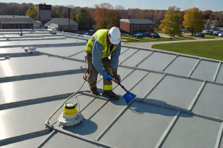
Commercial Engineering Dossier #860

Stripping Old Shingles Down to Clean Wood Sheathing Across Commercial Eaves on Commercial Pharmaceutical Production Facilitys

Industrial Building Envelope Sciences • Commercial Low-Slope Systems
Stripping Old Shingles Down to Clean Wood Sheathing Across Commercial Eaves on Commercial Pharmaceutical Production Facilitys

The Engineering Audit and Strategic Stripping Process

In the high-stakes environment of a pharmaceutical production facility, the building envelope is not merely a shelter but a critical component of the facility's containment and quality control strategy. When conducting an engineering audit on a facility with aging, multi-layer shingle systems, the primary objective is the total restoration of the substrate. Multi-layer roofing systems introduce excessive dead loads that can compromise the structural integrity of the eaves and rafter tails, often masking deep-seated rot or fastener fatigue. Our approach begins with a systematic, phased stripping process designed to minimize vibration and dust infiltration into the production zones below.

The removal process is executed using pneumatic tear-off equipment calibrated for precision to avoid gouging the underlying sheathing. We prioritize the removal of all asphaltic layers, including the underlying felt and saturated underlayments, to expose the raw wood sheathing. This "clean wood" state is the only acceptable baseline for a commercial audit, as it allows for the visual inspection of the wood's cellular structure and the identification of fungal decay or moisture-induced delamination.

  • Assessment of dead load accumulation from legacy shingle layers.
  • Implementation of dust mitigation protocols to protect pharmaceutical clean rooms.
  • Systematic removal of asphaltic membranes to expose the original decking.
  • Identification of localized saturation points at the eave transitions.
  • Verification of sheathing species and thickness against original architectural blueprints.

Fastener Withdrawal Resistance and Substrate Integrity

Once the sheathing is exposed, the focus shifts to the material science of the fasteners. In commercial roofing, the connection between the decking and the rafters is the most common point of failure. We employ a rigorous fastener withdrawal resistance test to ensure that the wood has not undergone "pulping" or significant loss of shear strength due to long-term moisture exposure. This involves using a calibrated pull-tester to measure the force required to dislodge existing nails, ensuring they meet or exceed the minimum requirements set by ASTM standards for structural wood fasteners.

If the fasteners slide out with minimal resistance, it indicates that the wood fibers have degraded or that the fasteners have oxidized to the point of failure. This is particularly critical at the eaves, where the leverage of the roof's overhang puts the most stress on the fastener groups. We analyze the wood for signs of wet rot (brown rot) or dry rot, which alters the hygroscopic properties of the sheathing and renders it incapable of supporting a new, high-performance commercial membrane.

  • Execution of pull-tests to quantify fastener withdrawal resistance.
  • Analysis of nail oxidation and galvanic corrosion in coastal or industrial environments.
  • Evaluation of wood density and fiber integrity using moisture meters.
  • Mapping of "soft spots" where the substrate fails to meet load-bearing specifications.
  • Cross-referencing fastener patterns with ANSI standards for commercial roof decking.

Structural Remediation and Sistering of Compromised Rafters

When the audit reveals compromised rafters—typically characterized by sagging, splitting, or severe rot at the birdsmouth cut—structural remediation is mandatory. We do not believe in "patching" in a pharmaceutical environment; we believe in reinforcement. The process of sistering involves installing a new, structural-grade member alongside the existing rafter to redistribute the load. We utilize kiln-dried, pressure-treated lumber or LVL (Laminated Veneer Lumber) depending on the required span and load-bearing capacity of the eave.

The sistering process is executed with surgical precision. The new member is dressed to fit snugly against the original rafter, then secured using a staggered pattern of heavy-duty structural screws and construction adhesives. This creates a composite beam that increases the overall stiffness of the roof plane and eliminates the deflection that often leads to ponding water or membrane tearing. By reinforcing the rafters, we ensure that the building envelope can support the weight of modern, high-efficiency insulation and membrane systems without further settlement.

  • Selection of LVL or structural spruce-pine-fir for sistering members.
  • Application of high-strength structural adhesives to ensure full-grain contact.
  • Installation of staggered structural fasteners to prevent splitting of the old growth wood.
  • Verification of rafter plumb and level using laser leveling tools.
  • Recalculation of load distribution to ensure the eave can support snow and wind loads.

Establishing the Flat Decking Plane for Membrane Application

The final stage of the restoration is the establishment of a perfectly flat decking plane. In commercial roofing, an uneven substrate is the enemy of the membrane. High and low spots create stress concentrations and air pockets, which can lead to premature failure of the flashing or the membrane itself. We utilize a combination of mechanical grinding and precision shimming to bring the entire eave area into a uniform plane. This process ensures that the transition from the main roof field to the eaves is seamless and structurally sound.

Once the plane is established, we perform a final sanding of the wood sheathing to remove any remaining splinters, protrusions, or old nail heads. This creates a smooth, monolithic surface that allows for the optimal adhesion of the primary underlayment. By treating the wood sheathing as a precision-engineered component rather than a simple base, we provide the pharmaceutical facility with a building envelope that is impervious to leaks and structurally optimized for the next several decades of operation.

  • Mechanical grinding of high points to eliminate substrate protrusions.
  • Installation of tapered shims to fill voids and eliminate depressions.
  • Laser-guided verification of the decking plane across the entire eave width.
  • Final sanding of the substrate to ensure a smooth transition for the membrane.
  • Comprehensive final audit of the building envelope's continuity and seal.

Aquashield Roofing Corporation

4006 Morris Ct.
Chesapeake, VA 23323
Direct Line: 757-553-5191
GPS Coordinates: 36.755164, -76.353932

Official Facebook Updates

Virginia Beach Roofing Company - Roofing Service Virginia Beach VA, Roofing Contractor

585 S Birdneck Rd #106
Virginia Beach, VA 23451
Direct Line: +17576318100
Google Maps Plus Code: RXCX+V7 Virginia Beach, Virginia
GPS Coordinates: 36.822156, -76.001565
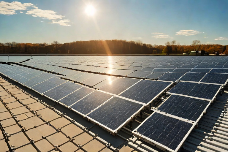
Commercial Engineering Dossier #861

Low-VOC Cold-Applied Adhesives & HVAC Air Intake Odor Mitigation Protocols on Commercial Historic Sanctuary & Education Annexs

Industrial Building Envelope Sciences • Commercial Low-Slope Systems
Low-VOC Cold-Applied Adhesives & HVAC Air Intake Odor Mitigation Protocols on Commercial Historic Sanctuary & Education Annexs

Envelope Audit and Historic Substrate Vulnerabilities

The structural integrity of a historic sanctuary and its accompanying education annex presents a unique set of engineering challenges, primarily due to the degradation of legacy building envelopes and the integration of modern HVAC systems into antiquated masonry. During the initial audit, we identified significant failures in the flashing interfaces and parapet caps, which had allowed moisture to migrate into the substrate via capillary action. The sanctuary's steep-slope transitions and the annex's flat-roof sections created complex drainage patterns that placed undue hydrostatic pressure on the existing membrane seams. Furthermore, the proximity of the primary HVAC air intake units to the roof's perimeter created a high-risk zone for the introduction of airborne contaminants during the remediation process.

Our engineering analysis focused on the "envelope-as-a-system" approach, recognizing that any intervention on the roofing surface could potentially compromise the interior air quality of the sanctuary. The historic nature of the building meant that the substrates were porous and prone to off-gassing if traditional solvent-based primers were used. We observed that the existing bitumen layers had become brittle, leading to micro-fractures that served as conduits for air leakage. To ensure a permanent seal, the strategy required a transition to a high-performance, cold-applied system that could bond to diverse substrates without the need for thermal welding, which would be too risky for the historic timber framing beneath the annex roof.

  • Identification of thermal bridging at the junction of the sanctuary spire and the main roof deck.
  • Analysis of moisture vapor transmission rates (MVTR) across the historic masonry walls.
  • Mapping of HVAC intake zones to establish "no-fume" buffer perimeters.
  • Evaluation of substrate tensile strength to determine the appropriate adhesive load-bearing capacity.

Material Science of Low-VOC Polyurethane Bonding Agents

To address the requirement for a zero-odor installation, we specified a high-modulus, low-VOC polyurethane bonding agent. Unlike traditional solvent-based adhesives that rely on the evaporation of volatile organic compounds to set, these modern polyurethane systems utilize a moisture-cure mechanism. This chemical reaction allows the adhesive to create a covalent bond with the substrate, ensuring a permanent, waterproof seal that maintains flexibility across a wide range of thermal expansion and contraction cycles. This is critical for the education annex, where seasonal temperature swings can cause significant movement in the building's structural steel and masonry.

From a material science perspective, the selection of a cold-applied system was mandated by the need to avoid the "heat-shock" associated with torch-down applications on historic substrates. The specified polyurethane adhesive meets stringent ASTM standards for peel strength and shear resistance, ensuring that the membrane remains adhered even under extreme wind-uplift conditions. The low-VOC formulation specifically eliminates the presence of toluene and xylene, which are the primary culprits behind the pungent odors typically associated with commercial roofing. By utilizing a rapid-setting, odorless polymer, we were able to achieve a high-strength bond that cures from the outside in, preventing the entrapment of gases that could lead to blistering.

  • Utilization of moisture-cure chemistry to eliminate solvent evaporation.
  • Adherence to ASTM D1874 for shear strength and long-term bonding stability.
  • Implementation of a high-modulus polymer to accommodate structural shifting in historic masonry.
  • Reduction of VOC emissions to below 50g/L to ensure compliance with indoor air quality standards.

HVAC Air Intake Containment and Odor Mitigation Protocols

The most critical phase of the engineering execution was the mitigation of odors near the HVAC air intakes. In a commercial sanctuary environment, the circulation of air is often centralized, meaning a single leak of adhesive fumes at the roof level could contaminate the entire interior sanctuary and education classrooms. To prevent this, we engineered a series of temporary containment barriers. These barriers consisted of reinforced polyethylene sheeting and negative-pressure vacuum zones, which effectively isolated the work area from the building's breathing apparatus. We established a strict "containment perimeter" around each intake, ensuring that no adhesives were applied within a ten-foot radius without a sealed shroud.

Furthermore, we implemented a synchronized ventilation protocol. This involved coordinating with the building's facilities manager to switch the HVAC system to 100% outdoor air recirculation during the application of the bonding agents, followed by a period of total intake shutdown during the most critical curing windows. By monitoring the air pressure differentials between the roof surface and the interior ceilings, we ensured that the building remained under slight positive pressure, pushing any stray molecules away from the interior. This rigorous approach to air management transformed a high-risk operation into a controlled engineering process, ensuring that the sanctuary's congregation and students remained undisturbed.

  • Installation of airtight polyethylene shrouds over all HVAC intake vents.
  • Deployment of portable HEPA-filtered air scrubbers to neutralize ambient particles.
  • Implementation of a "Positive Pressure" interior strategy to block fume infiltration.
  • Real-time monitoring of VOC levels using handheld photoionization detectors (PIDs).

Zero-Downtime Execution and Engineering Validation

The mandate for zero-downtime execution required a phased approach to the roofing application. We divided the education annex and sanctuary roof into four distinct quadrants, allowing us to isolate and seal one section while the others remained fully operational. The use of rapid-setting adhesives was paramount here; by selecting a product with a fast "tack-free" time, we were able to move the membrane into its final position and secure the seams in a fraction of the time required for traditional systems. This efficiency minimized the window of vulnerability and allowed for immediate foot traffic upon the completion of each quadrant.

Following the application, a comprehensive engineering validation was conducted to ensure the envelope's integrity. This included infrared thermography to detect any remaining thermal leaks and electronic leak detection (ELD) to verify the continuity of the membrane. The results confirmed that the low-VOC polyurethane system had created a monolithic seal across the entire roof surface, effectively eliminating all points of infiltration. The final audit verified that the bonding agents had achieved full cure without any shrinkage or void formation, providing the historic structure with a modern, durable shield that protects both the architectural heritage and the occupants within.

  • Phased quadrant execution to maintain building occupancy and operations.
  • Use of rapid-set polymers to reduce the curing window and accelerate project timelines.
  • Post-installation infrared scanning to validate thermal performance and seal continuity.
  • Final engineering sign-off based on ASTM E1105 for water resistance and air leakage.

Aquashield Roofing Corporation

4006 Morris Ct.
Chesapeake, VA 23323
Direct Line: 757-553-5191
GPS Coordinates: 36.755164, -76.353932

Official Facebook Updates

Virginia Beach Roofing Company - Roofing Service Virginia Beach VA, Roofing Contractor

585 S Birdneck Rd #106
Virginia Beach, VA 23451
Direct Line: +17576318100
Google Maps Plus Code: RXCX+V7 Virginia Beach, Virginia
GPS Coordinates: 36.822156, -76.001565
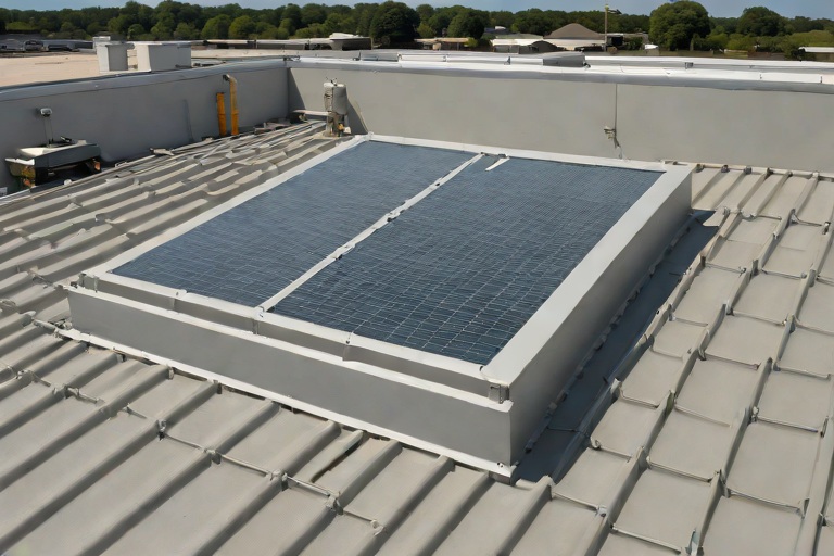
Commercial Engineering Dossier #862

Solar Photovoltaic Ballasted Racking Point-Load Defense & Sacrificial Slip Sheets on Commercial Financial Institution Data Vaults

Industrial Building Envelope Sciences • Commercial Low-Slope Systems
Solar Photovoltaic Ballasted Racking Point-Load Defense & Sacrificial Slip Sheets on Commercial Financial Institution Data Vaults

The Engineering Challenge of Ballasted PV on Critical Infrastructure

When auditing the building envelope of a financial institution data vault, the margin for error is zero. Unlike a standard commercial warehouse, a data vault houses mission-critical server arrays where a single roof leak can result in catastrophic hardware failure and millions of dollars in lost data. The primary engineering challenge arises when integrating Solar Photovoltaic (PV) systems using ballasted racking. While ballasted systems are preferred because they avoid structural penetrations, they introduce significant point-load stresses that can compromise the roof's integrity over time.

The physics of a ballasted system rely on heavy concrete blocks to counteract wind uplift. However, this concentrated weight creates a high-pressure zone on the roof membrane, leading to what we define as localized compression. If the load is not properly distributed, the membrane can undergo permanent deformation, effectively "bottoming out" against the roof insulation and decking. This creates a dip in the roof profile that encourages ponding water, which in turn accelerates the degradation of the flashing and seams.

  • Point-Load Concentration: The concentration of thousands of pounds of concrete on small footprints of TPO or PVC membrane.
  • Structural Deflection: The subtle bowing of the roof deck under the weight of the PV array, which can stress the perimeter flashing.
  • Wind Uplift Dynamics: The risk of "scouring," where the racking system shifts slightly during high-wind events, grinding the ballast against the membrane.
  • Thermal Expansion: The differential movement between the metal racking and the thermoplastic membrane during extreme temperature cycles.

Mitigating Compression Set via High-Density Slip-Sheet Barriers

To prevent the aforementioned compression set, Aquashield Corporate implements a rigorous sacrificial slip-sheet protocol. A compression set occurs when the cellular structure of the roof insulation is crushed beyond its ability to recover, creating a permanent indentation. In a data vault environment, this is unacceptable. We utilize heavy-duty, non-woven polyester or reinforced rubber slip-sheets placed directly beneath every ballast block and racking rail. These sheets act as a load-distribution layer, spreading the vertical force across a wider surface area of the membrane.

From a material science perspective, the slip-sheet serves as a sacrificial abrasion barrier. The coefficient of friction between a concrete block and a TPO membrane is high enough that any micro-movement caused by thermal expansion or wind can lead to "membrane scrubbing." By introducing a high-density polymer barrier, we ensure that the friction occurs between the ballast and the slip-sheet, rather than the ballast and the primary waterproofing layer. This preserves the tensile strength of the roof membrane and ensures that the building envelope remains airtight and watertight.

  • Material Specification: Use of 60-mil reinforced rubber or high-density polyethylene (HDPE) sheets for maximum durability.
  • Load Distribution: Increasing the footprint of the load to reduce the PSI (pounds per square inch) exerted on the insulation.
  • Abrasion Resistance: Preventing the "sandpaper effect" of concrete against thermoplastic membranes during wind-induced vibration.
  • ASTM Compliance: Ensuring all barrier materials meet ASTM standards for UV resistance and chemical compatibility with the roof membrane.

Pre-fabricated Target Patches and Targeted Reinforcement

A master roofer knows that the most vulnerable part of a roof is not the field, but the areas of highest stress. For financial data vaults, we employ a "Target Patch" strategy. Before the PV racking is installed, we identify the exact coordinates where the ballast blocks will sit. We then install pre-fabricated, oversized reinforcement patches—essentially a "roof within a roof"—at these specific points. These patches are heat-welded or chemically bonded to the main membrane, providing an extra layer of defense against punctures and punctures from debris that may get trapped under the racking.

This approach is critical for the long-term lifecycle of the building. When the PV system reaches its end-of-life in 20 to 25 years, or if a specific panel needs to be replaced, the removal of the ballast blocks often reveals the most worn sections of the roof. By utilizing target patches, we ensure that the primary waterproofing layer has never been directly exposed to the crushing weight of the ballast. This eliminates the need for extensive roof replacement during the decommissioning of the solar array, as the primary membrane remains pristine beneath the sacrificial layers.

  • Strategic Placement: Mapping the racking layout to ensure 100% coverage of all high-pressure points.
  • Welding Integrity: Utilizing dual-track heat welding to ensure the target patches are fully integrated into the field membrane.
  • Redundancy: Creating a multi-layered defense system that allows for the failure of the slip-sheet without compromising the vault.
  • Maintenance Access: Allowing technicians to move equipment across the roof without risking punctures to the main envelope.

Cable Tray Routing and Envelope Penetration Management

The final critical component of the building envelope audit is the management of electrical conduits and cable trays. In a data vault, the transition from the rooftop PV array to the interior electrical room is a high-risk zone. Improperly routed cable trays can create "rub points" where the metal tray vibrates against the roof membrane, eventually wearing through the material. Furthermore, cables that are not properly secured can act as conduits for water, leading runoff directly into the building's interior via capillary action.

Our engineering standard requires the use of elevated, non-penetrating cable supports. These supports are designed to keep the cabling off the roof surface, preventing the accumulation of debris and standing water beneath the trays. Where the cables must finally penetrate the roof to enter the vault, we utilize a comprehensive flashing system consisting of a reinforced curb, a liquid-applied flashing membrane, and a mechanical counter-flashing. This ensures a redundant, multi-stage seal that prevents moisture ingress while maintaining the thermal envelope of the facility.

  • Vibration Isolation: Using rubberized gaskets between cable trays and supports to prevent membrane abrasion.
  • Water Shedding: Routing trays to follow the natural slope of the roof, avoiding any "damming" effect that could lead to ponding.
  • Penetration Sealing: Implementing a three-stage sealing process (primary membrane, liquid flashing, and metal cladding) at all entry points.
  • Thermal Bridging Mitigation: Using insulated conduits to prevent heat loss from the data vault and reduce the risk of interior condensation.

Aquashield Roofing Corporation

4006 Morris Ct.
Chesapeake, VA 23323
Direct Line: 757-553-5191
GPS Coordinates: 36.755164, -76.353932

Official Facebook Updates

Virginia Beach Roofing Company - Roofing Service Virginia Beach VA, Roofing Contractor

585 S Birdneck Rd #106
Virginia Beach, VA 23451
Direct Line: +17576318100
Google Maps Plus Code: RXCX+V7 Virginia Beach, Virginia
GPS Coordinates: 36.822156, -76.001565

Commercial Engineering Dossier #863

OSHA-Compliant Skylight Fall-Protection Curbs & Heavy-Duty Security Screens on Commercial Telecommunications Central Switching Offices

Industrial Building Envelope Sciences • Commercial Low-Slope Systems
OSHA-Compliant Skylight Fall-Protection Curbs & Heavy-Duty Security Screens on Commercial Telecommunications Central Switching Offices

The Criticality of Envelope Integrity in Telecommunications Central Switching Offices

Central Switching Offices (CSOs) represent the most critical nodes in telecommunications infrastructure. Unlike standard commercial warehouses, these facilities house high-density switching gear, massive power arrays, and sensitive fiber-optic termination points. The building envelope, therefore, is not merely a shell but a primary line of defense for mission-critical hardware. When auditing these structures, the primary concern is the intersection of safety compliance and moisture mitigation. Skylights, while necessary for natural light and emergency egress, represent inherent vulnerabilities in the roof plane. A failure in the skylight curb flashing or a collapse of a fall-protection screen can lead to catastrophic water intrusion or life-safety violations.

From an engineering perspective, the integration of OSHA-compliant fall protection on these roofs requires a rigorous adherence to ANSI Z359 standards. In a CSO environment, we cannot afford "standard" installations; we require precision-engineered systems that account for the high-frequency vibration of HVAC equipment and the potential for extreme thermal expansion. The objective is to create a seamless transition from the primary roofing membrane to the skylight curb, ensuring that the fall-protection screens do not compromise the watertight integrity of the building envelope.

  • Adherence to OSHA 1910.28 regarding fall protection systems for holes and openings.
  • Mitigation of "single point of failure" risks in the roof-to-curb transition.
  • Protection of sensitive electronic equipment from moisture ingress during screen installation.
  • Alignment with ASTM E2128 for standard penetration testing of the building envelope.

Engineering Fall-Arrest Anchoring and Load Distribution

The primary engineering challenge for skylight security screens is the 200-lb point-load requirement. OSHA mandates that fall-protection systems must be capable of supporting the applied load of an employee falling from the working level. In the context of a CSO, where roof decks are often a combination of reinforced concrete and corrugated steel, the anchoring system must be calculated to prevent "pull-out" failure. We utilize a high-strength steel frame for the security screens, which is then mechanically fastened to the curb's structural members rather than the flashing itself. This ensures that the load is transferred directly to the building's primary structure.

When calculating the anchoring, we evaluate the shear and tension forces acting upon the fasteners. For concrete substrates, we specify heavy-duty stainless steel expansion anchors or chemical adhesives to prevent corrosion and ensure a permanent bond. For steel decks, we employ oversized load-spreading washers to prevent the fastener from "zipping" through the deck during a high-impact event. The security screen is not merely a cage; it is a structural component of the roof's safety system, requiring precise tolerances to avoid creating gaps where wind-driven rain could be forced under the membrane.

  • Utilization of Grade 5 or higher galvanized fasteners to prevent galvanic corrosion.
  • Calculation of load distribution across a minimum of four primary anchoring points per screen.
  • Implementation of safety factors (typically 5:1) to exceed minimum ANSI requirements.
  • Verification of substrate integrity through ultrasonic testing or core sampling before anchor placement.

Curb Flashing Elevation and Water Shedding Dynamics

Water is the enemy of the CSO. The transition from the flat roof membrane to the vertical face of the skylight curb is a frequent site of failure. To ensure a permanent seal, we implement a rigorous curb flashing elevation strategy. The flashing must extend a minimum of 8 inches above the finished roof surface to prevent "splash-back" and wind-driven rain from infiltrating the interior. We employ a multi-layered approach: the primary membrane is wrapped up the curb, followed by a reinforced flashing membrane, and finally capped with a custom-fabricated metal counter-flashing. This creates a redundant system where water is mechanically shed away from the curb's interior.

The geometry of the flashing is critical. We avoid 90-degree angles, which can create stress points in the membrane, and instead utilize gradual radii to allow the material to flow naturally. The integration of the fall-protection screen must not puncture this flashing. To achieve this, the screens are designed to sit slightly proud of the flashing, with the anchoring hardware passing through sealed gaskets. This ensures that the "shingle effect" is maintained, meaning every layer of the envelope overlaps in a way that directs water downward and outward, never inward.

  • Implementation of a 45-degree cant strip at the base of the curb to reduce membrane stress.
  • Use of high-performance flashing adhesives that maintain flexibility across a wide temperature range.
  • Installation of drip edges on the counter-flashing to prevent capillary action.
  • Strict adherence to the "top-down" flashing sequence to ensure total water shedding.

Thermal Gaskets and Compression Termination Bars

The final seal of the skylight assembly relies on the science of compression and material elasticity. Because CSOs experience significant thermal cycling due to the heat generated by internal switching equipment, the roof envelope is subject to constant expansion and contraction. To prevent the seals from cracking or pulling away, we utilize closed-cell EPDM or silicone thermal gaskets. These gaskets provide a continuous, airtight seal between the security screen frame and the curb, acting as a buffer that absorbs movement without losing its compressive force.

To lock these gaskets in place, we employ heavy-duty aluminum compression termination bars. These bars are mechanically fastened at 6-inch intervals, applying uniform pressure across the entire perimeter of the seal. This "sandwich" effect—membrane, gasket, and termination bar—creates a redundant barrier against air infiltration and moisture. The termination bar also serves a dual purpose: it protects the edge of the roofing membrane from mechanical damage and provides a clean, professional finish that is easy to inspect during annual audits. By focusing on these minute details of material science, we ensure the CSO remains a secure, dry, and OSHA-compliant facility.

  • Selection of gaskets with a high Shore A hardness rating to resist compression set.
  • Use of stainless steel fasteners for termination bars to eliminate rust streaks on the roof.
  • Application of a bead of high-grade sealant behind the termination bar for secondary redundancy.
  • Verification of seal integrity using vacuum testing or infrared thermography.

Aquashield Roofing Corporation

4006 Morris Ct.
Chesapeake, VA 23323
Direct Line: 757-553-5191
GPS Coordinates: 36.755164, -76.353932

Official Facebook Updates

Virginia Beach Roofing Company - Roofing Service Virginia Beach VA, Roofing Contractor

585 S Birdneck Rd #106
Virginia Beach, VA 23451
Direct Line: +17576318100
Google Maps Plus Code: RXCX+V7 Virginia Beach, Virginia
GPS Coordinates: 36.822156, -76.001565
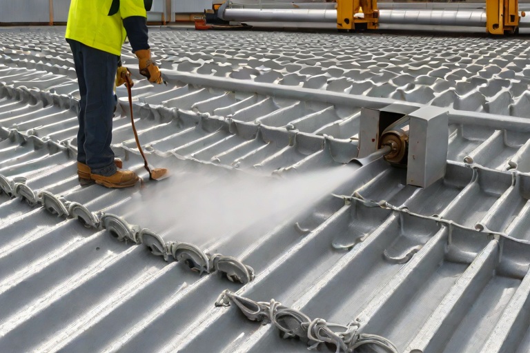
Commercial Engineering Dossier #864

Rooftop Mechanical Unit Vibration Isolation Rails & Spring-Mounted Curb Seals on Commercial Heavy Manufacturing Fabrication Plants

Industrial Building Envelope Sciences • Commercial Low-Slope Systems
Rooftop Mechanical Unit Vibration Isolation Rails & Spring-Mounted Curb Seals on Commercial Heavy Manufacturing Fabrication Plants

The Dynamics of Harmonic Vibration in Heavy Manufacturing Environments

In the context of heavy manufacturing fabrication plants, the rooftop is not merely a weather barrier; it is a critical structural component subjected to extreme kinetic energy. Large-scale HVAC units, industrial exhaust fans, and heavy-duty compressors generate significant harmonic vibrations. When these units are mounted on traditional rigid curbs, the mechanical energy is transferred directly into the roof deck and the building's primary structural steel. This phenomenon, known as structural resonance, can lead to accelerated fatigue of the roof membrane and the premature failure of fastening systems.

From an engineering perspective, the goal is to decouple the mechanical equipment from the building envelope. If the vibration frequency of the equipment matches the natural frequency of the roof assembly, the resulting amplification can cause microscopic fissures in the waterproofing layers. Over time, these fissures evolve into systemic leaks, often appearing as "star-pattern" cracks around the perimeter of the equipment curb. To mitigate this, we implement a rigorous adherence to ASTM standards regarding vibration isolation and structural loading.

  • Analysis of low-frequency oscillations to determine the required spring rate for isolation.
  • Evaluation of the roof deck's load-bearing capacity to ensure the isolation rails do not create point-load failures.
  • Assessment of the coefficient of friction between the equipment base and the mounting rail.
  • Identification of harmonic nodes where vibration is most likely to cause membrane shear.

Engineering Spring-Isolated Equipment Curbs and Rails

To solve the problem of energy transfer, we move away from rigid curb construction in favor of spring-mounted vibration isolation rails. These systems utilize heavy-duty helical steel springs designed to absorb and dissipate kinetic energy before it reaches the roof substrate. The isolation rail acts as a buffer, ensuring that the mechanical unit "floats" relative to the roof surface. This is particularly critical in fabrication plants where machinery may cycle on and off, creating sudden torque shifts and jarring movements that would otherwise tear a standard flashing membrane.

The installation of these rails requires precision alignment and a deep understanding of load distribution. We utilize reinforced steel channels that distribute the weight across a broader area of the roof deck, reducing the stress on any single joist. By integrating these spring mounts, we effectively shift the natural frequency of the system, ensuring that the equipment operates outside the resonance range of the building's envelope. This prevents the "drumming" effect that often leads to the backing out of fasteners and the subsequent compromise of the watertight seal.

  • Implementation of open-spring isolators for maximum deflection and vibration absorption.
  • Utilization of neoprene leveling pads to provide secondary high-frequency damping.
  • Strategic placement of rail supports to align with structural steel beams rather than the center of the roof deck.
  • Calibration of spring tension based on the operational weight and centrifugal force of the mechanical units.

Fiber-Reinforced Structural Mastic and Watertight Integrity

The most vulnerable point of any rooftop mechanical installation is the interface between the moving equipment and the static roof membrane. Traditional sealants and flashing membranes are often too rigid to withstand the constant, minute oscillations of a spring-isolated unit. When a unit moves, a rigid seal will inevitably crack or delaminate. To counter this, we employ fiber-reinforced structural mastic. This material is engineered with a high elongation percentage and internal reinforcement that allows it to stretch and contract without losing its cohesive bond to the substrate.

The application process involves a multi-stage layering technique. First, a primer is applied to ensure a molecular bond between the roof membrane and the curb. Then, the fiber-reinforced mastic is applied in wide, overlapping passes, creating a flexible "boot" around the base of the isolation rail. This creates a redundant waterproofing system: the mastic provides the primary seal, while the fiber reinforcement prevents the propagation of tears. This approach ensures that the building envelope remains hermetically sealed, even as the mechanical unit undergoes thousands of vibration cycles per hour.

  • Application of high-solids, polymer-modified mastic for superior adhesion to TPO, PVC, and EPDM membranes.
  • Integration of non-woven reinforcement fabrics to increase the tear strength of the curb seals.
  • Use of flashing-grade sealants that maintain flexibility across a wide range of thermal extremes.
  • Implementation of a "floating" flashing detail that allows for differential movement between the rail and the roof.

Envelope Integrity Audits and Lifecycle Maintenance

A master-level engineering approach does not end with installation; it extends into a rigorous audit cycle. For heavy manufacturing plants, we conduct quarterly building envelope audits specifically targeting the mechanical interfaces. These audits utilize infrared thermography to detect hidden moisture penetration and ultrasonic testing to identify voids in the structural mastic. Because vibration is a constant force, the "creep" of materials is inevitable. We monitor the compression of the spring mounts and the elasticity of the seals to predict failure before it occurs.

The lifecycle of a rooftop system in a high-vibration environment is determined by the quality of the initial decoupling and the consistency of the maintenance. Our audit process focuses on the "critical failure zones"—the corners of the curbs and the fastener penetrations. By identifying early signs of stress, such as hairline fractures in the mastic or the loosening of rail bolts, we can perform surgical repairs that extend the life of the roof by decades. This proactive strategy transforms the roof from a liability into a durable asset that supports the plant's operational uptime.

  • Quarterly visual inspections of all spring-mounted curbs for signs of metal fatigue or spring collapse.
  • Annual moisture probes around the perimeter of mechanical rails to verify seal integrity.
  • Verification of fastener torque specifications to ensure isolation rails remain securely anchored.
  • Assessment of UV degradation on exposed mastic seals and application of protective coatings.

Aquashield Roofing Corporation

4006 Morris Ct.
Chesapeake, VA 23323
Direct Line: 757-553-5191
GPS Coordinates: 36.755164, -76.353932

Official Facebook Updates

Virginia Beach Roofing Company - Roofing Service Virginia Beach VA, Roofing Contractor

585 S Birdneck Rd #106
Virginia Beach, VA 23451
Direct Line: +17576318100
Google Maps Plus Code: RXCX+V7 Virginia Beach, Virginia
GPS Coordinates: 36.822156, -76.001565

Commercial Engineering Dossier #865

Structural Steel Deck Rust Remediation & Zinc-Rich Primer Passivation on Commercial Logistics Distribution Hubs

Industrial Building Envelope Sciences • Commercial Low-Slope Systems
Structural Steel Deck Rust Remediation & Zinc-Rich Primer Passivation on Commercial Logistics Distribution Hubs

Diagnostic Audit of Atmospheric Corrosion in Large-Scale Logistics Hubs

In the high-volume environment of a commercial logistics distribution hub, the building envelope is subject to extreme thermal fluctuations and internal humidity spikes. As a master commercial roofer and building envelope specialist, my primary objective during an engineering audit is to identify the onset of atmospheric corrosion on the structural steel decking. In these massive footprints, the steel deck serves as both the primary diaphragm for lateral stability and the substrate for the roofing assembly. When the vapor barrier is compromised or when condensation occurs due to poor ventilation, moisture accumulates in the flutes of the deck, initiating an oxidation process that threatens the structural integrity of the entire facility.

The audit process begins with a comprehensive visual inspection and a tactile assessment of the steel's surface. We look for signs of "pitting" and "scaling," which indicate that the oxidation has moved beyond a superficial layer and is now compromising the gauge of the steel. In logistics hubs, this is often exacerbated by the movement of heavy machinery and the resulting vibrations, which can create micro-fissures in existing coatings. We evaluate the corrosion levels based on the degree of surface degradation, ensuring that we distinguish between cosmetic flash rust and structural section loss.

  • Assessment of moisture ingress points through the roof membrane or wall flashing.
  • Evaluation of "sweating" patterns on the underside of the steel deck caused by thermal bridging.
  • Measurement of steel thickness using ultrasonic gauges to determine the percentage of section loss.
  • Mapping of high-corrosion zones, typically found near HVAC exhaust vents and loading dock portals.
  • Verification of existing coating adhesion using ASTM D3359 standards to identify delamination.

Mechanical Remediation and Surface Preparation Protocols

Once the diagnostic audit identifies areas of active oxidation, the remediation phase begins with rigorous mechanical surface preparation. It is a fundamental rule of commercial roofing engineering that no chemical treatment is effective if the substrate is not properly cleaned. We employ a systematic wire-brushing and grinding approach to remove all loose scale, rust, and degraded paint. This process is designed to achieve a surface profile that allows for maximum mechanical bonding of the subsequent primer. We adhere to the Society for Protective Coatings (SSPC) standards, specifically targeting an SSPC-SP2 or SP3 finish, which ensures the removal of all loose mill scale and oxidation.

The precision of the wire-brushing process is critical; over-brushing can lead to further thinning of already compromised steel, while under-brushing leaves behind microscopic pockets of rust that can lead to "under-film" corrosion. Our crews utilize pneumatic power-brushing tools to ensure consistency across the wide spans of the distribution hub. After the mechanical removal of rust, the surface is cleaned with a solvent-based degreaser to remove any residual oils or particulates that could interfere with the chemical bond of the passivation layer.

  • Utilization of heavy-duty pneumatic wire wheels for rapid removal of oxidized layers.
  • Application of abrasive grinding discs to smooth out pitted surfaces and create a uniform profile.
  • Implementation of vacuum-assisted dust collection to prevent airborne contaminants from settling on cleaned steel.
  • Detailed cleaning of the flute bottoms where moisture and debris typically accumulate.
  • Final solvent wipe-down to ensure a chemically clean surface prior to primer application.

Chemical Passivation via High-Solids Zinc-Rich Primers

With the steel substrate cleaned and profiled, we move to the passivation phase. The goal is to stop the oxidation process and provide a long-term barrier against future corrosion. We utilize high-solids, zinc-rich rust-inhibiting primers, which function through a process known as galvanic protection. In this electrochemical reaction, the zinc acts as a sacrificial anode. Because zinc is more electronegative than steel, it corrodes preferentially, effectively "sacrificing" itself to protect the underlying iron from oxidation. This is not merely a coating; it is a chemical transformation of the surface environment that prevents the formation of iron oxide.

The application of the primer must be precise to ensure total coverage of the steel flutes. We apply the primer in a thin, uniform layer, ensuring that the edges of the deck and the fastener heads are fully encapsulated. The high solids content of the primer ensures that once the solvent evaporates, a dense, non-porous layer of zinc remains. This passivation layer is critical in logistics hubs where the environment may be subject to chemical fumes or high humidity, as it creates an impermeable shield that prevents oxygen and moisture from reaching the raw steel.

  • Application of organic zinc-rich primers to provide superior flexibility and adhesion.
  • Ensuring a Dry Film Thickness (DFT) that meets engineering specifications for industrial environments.
  • Verification of cure times to ensure the primer has fully passivated before the installation of insulation or decking covers.
  • Application of a secondary topcoat where additional chemical resistance is required.
  • Monitoring of ambient temperature and humidity to ensure optimal primer polymerization.

Structural Restoration of Thinned Flutes and Fastener Stabilization

In cases where the audit reveals significant section loss—where the rust has eaten through a substantial percentage of the steel gauge—simple priming is insufficient. We must perform structural reinforcement to restore the diaphragm action of the deck. This involves the installation of steel reinforcement plates or the welding of reinforcement strips to the thinned flutes. By reinforcing these areas, we ensure that the deck can still support the dead load of the roofing system and the live loads of maintenance personnel without risking a structural failure or a "punch-through" event.

Finally, we address the integrity of the fasteners. Corrosion often concentrates around the fasteners because the penetration of the steel creates a point of vulnerability. We inspect every fastener for "necking" or head degradation. If a fastener is compromised, it is removed and replaced with a heavy-duty, galvanized fastener that is torqued to the specific ANSI standards for the deck gauge. This ensures that the roofing membrane is securely anchored and that the structural deck remains tightly integrated with the primary support beams, eliminating any gaps that could allow moisture to seep back into the system.

  • Welding of reinforcement plates to areas with more than 20% section loss.
  • Replacement of corroded fasteners with high-strength, hot-dipped galvanized alternatives.
  • Torque-testing of all structural fasteners to ensure maximum pull-out resistance.
  • Application of zinc-rich primer to all new welds and reinforcement plates to prevent galvanic corrosion.

Aquashield Roofing Corporation

4006 Morris Ct.
Chesapeake, VA 23323
Direct Line: 757-553-5191
GPS Coordinates: 36.755164, -76.353932

Official Facebook Updates

Virginia Beach Roofing Company - Roofing Service Virginia Beach VA, Roofing Contractor

585 S Birdneck Rd #106
Virginia Beach, VA 23451
Direct Line: +17576318100
Google Maps Plus Code: RXCX+V7 Virginia Beach, Virginia
GPS Coordinates: 36.822156, -76.001565

Commercial Engineering Dossier #866

Hands-On Physical Roof Inspections & Boots-on-the-Roof Forensic Maintenance Audits on Commercial Automotive Assembly Plants

Industrial Building Envelope Sciences • Commercial Low-Slope Systems
Hands-On Physical Roof Inspections & Boots-on-the-Roof Forensic Maintenance Audits on Commercial Automotive Assembly Plants

The Forensic Philosophy of Automotive Assembly Envelopes

In the realm of commercial building envelope engineering, an automotive assembly plant represents one of the most challenging environments for roof asset management. These facilities are characterized by massive footprints, complex HVAC integrations, and constant internal vibrations caused by heavy robotic stamping and assembly lines. A standard visual inspection is insufficient for these structures; a true forensic audit requires a "boots-on-the-roof" approach that prioritizes physical tactile verification over remote sensing. When we evaluate an envelope of this scale, we are not looking for obvious ponding or daylight; we are searching for systemic failures in the material science and mechanical fastening systems that precede a catastrophic leak.

The objective of a forensic maintenance audit is to identify the "silent failures" that occur at the microscopic or mechanical level. In automotive plants, thermal cycling is extreme due to the heat generated by industrial curing ovens and painting booths, which creates significant expansion and contraction stresses on the roof membrane and metal panels. This constant movement puts immense pressure on the seams and fasteners, often leading to fatigue that is invisible to the naked eye but easily detectable through rigorous physical probing.

  • Evaluation of substrate stability and deflection under heavy equipment loads.
  • Analysis of thermal bridging at penetration points and curb flashes.
  • Assessment of chemical off-gassing from assembly processes that may degrade polymer membranes.
  • Verification of wind-uplift resistance in accordance with ANSI/SPHIA standards.

Mechanical Integrity and Automated Seam Analysis

Modern automotive plants often utilize automated seaming machines to ensure consistency across thousands of linear feet of roofing. However, automation is not infallible. "Holidays"—small gaps or voids in the seam—can occur when the machine encounters a slight misalignment in the panel or a momentary drop in hydraulic pressure. A master roofer knows that a seam may look closed from a distance, but a physical probe reveals the truth. We utilize specialized hand tools, such as calibrated seam gauges and precision probes, to manually check the integrity of these folds.

The process involves a systematic "probing" technique where the tool is inserted into the seam to check for complete closure and the presence of a continuous sealant bead. If the probe encounters resistance-free movement or "play" in the seam, it indicates a failure in the mechanical lock. This is critical because a failed seam in an automotive plant doesn't just let in water; it allows pressurized air and industrial pollutants to enter the building, potentially compromising the clean-room environments required for vehicle painting and final assembly.

  • Tactile verification of standing seam engagement to ensure full mechanical lock.
  • Probing of lap joints to identify "cold welds" or insufficient crimping in automated folds.
  • Testing the elasticity of sealant beads to ensure they have not become brittle due to UV exposure.
  • Mapping of seam failure patterns to determine if the issue is systemic to the installation equipment.

Critical Point Failure: Drain Bowls and Perimeter Cleats

The most vulnerable points of any commercial roof are where the water is managed and where the roof ends. In an automotive assembly plant, the drain bowl is a high-stress zone. We focus heavily on clamping torque; if the clamping rings are under-torqued, the seal between the membrane and the drain bowl will fail during a heavy rain event due to the sheer volume of water weight. Conversely, over-torquing can crush the gasket or distort the metal, creating a capillary path for water to enter. We utilize calibrated torque wrenches to ensure every bolt meets the manufacturer's engineering specifications.

Similarly, the perimeter cleats—the components that secure the roof edges—are subject to the highest wind-uplift forces. In a forensic audit, we inspect for "peeling" or "backing out" of the fasteners. We examine the interface between the drip edge and the fascia, ensuring that the perimeter is not just fastened, but engineered to breathe. If the cleats are too rigid, the thermal expansion of the roof can buckle the metal; if they are too loose, the wind can get under the membrane and initiate a progressive failure of the entire edge system.

  • Measurement of clamping torque on all primary drain assemblies to prevent gasket failure.
  • Inspection of perimeter cleat spacing and fastener embedment depth.
  • Verification of flashing integrity at the transition from roof to parapet wall.
  • Analysis of scupper clearance and the absence of debris-induced backup.

Engineering Documentation and Lifecycle Reporting

A forensic audit is only as valuable as the written report that follows. A master roofer does not provide a "to-do list"; we provide an engineering document that correlates physical findings with material science. Our reporting structure for Aquashield Corporate focuses on the "Root Cause Analysis" (RCA). Instead of stating that a seam is leaking, the report specifies that the seam failed due to excessive thermal movement and insufficient lap length, citing the specific ASTM standards for the material in question.

This level of detail transforms the report from a simple repair list into a lifecycle management tool. By documenting the exact location and nature of every failure, we can predict the remaining useful life (RUL) of the roof system. This allows the plant operators to move from a reactive maintenance posture—where they are chasing leaks—to a proactive engineering posture, where they are scheduling targeted remediations based on hard data. This approach minimizes operational downtime and protects the multi-million dollar assets beneath the roof.

  • Creation of a detailed "Defect Map" utilizing GPS coordinates for every identified failure.
  • Categorization of findings into "Immediate Critical," "Scheduled Maintenance," and "Observation."
  • Correlation of leak patterns with internal plant vibration and heat maps.
  • Provision of long-term capital expenditure (CapEx) forecasts based on material degradation rates.

Aquashield Roofing Corporation

4006 Morris Ct.
Chesapeake, VA 23323
Direct Line: 757-553-5191
GPS Coordinates: 36.755164, -76.353932

Official Facebook Updates

Virginia Beach Roofing Company - Roofing Service Virginia Beach VA, Roofing Contractor

585 S Birdneck Rd #106
Virginia Beach, VA 23451
Direct Line: +17576318100
Google Maps Plus Code: RXCX+V7 Virginia Beach, Virginia
GPS Coordinates: 36.822156, -76.001565
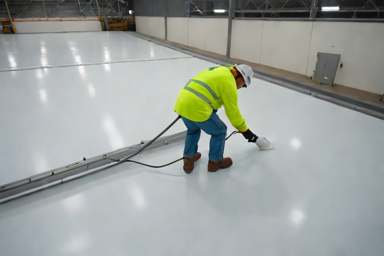
Commercial Engineering Dossier #867

60-Mil TPO Robotic Hot-Air Seam Fusion & Test-Cut Peel Audits on Commercial Mission-Critical Data Centers

Industrial Building Envelope Sciences • Commercial Low-Slope Systems
60-Mil TPO Robotic Hot-Air Seam Fusion & Test-Cut Peel Audits on Commercial Mission-Critical Data Centers

The Engineering Imperative of the Mission-Critical Data Center Envelope

In the realm of commercial building envelopes, few assets demand the level of precision required for mission-critical data centers. Unlike standard warehouse or retail structures, a data center houses millions of dollars in server infrastructure where a single pinpoint leak can lead to catastrophic equipment failure and unplanned downtime. The roof is not merely a cover; it is the primary defense mechanism of the facility. For these high-stakes environments, we specify a 60-mil TPO (Thermoplastic Polyolefin) membrane, providing a robust thickness that resists puncture and offers superior long-term UV stability compared to thinner 45-mil alternatives.

The objective of a professional engineering audit is to ensure that the membrane has been transformed from individual sheets into a monolithic, single-ply waterproof shield. This is achieved through hot-air fusion, a process that melts the polymer chains of the overlapping membranes, fusing them at a molecular level. When executed correctly, the seam becomes the strongest part of the roof system, often exceeding the tensile strength of the membrane itself.

  • Requirement for zero-leak tolerance in Tier III and Tier IV data center facilities.
  • Utilization of 60-mil TPO to enhance puncture resistance and thermal bridging mitigation.
  • Focus on the transition from mechanical fastening to chemical/thermal fusion.
  • The necessity of a comprehensive building envelope audit to validate installation quality.

Robotic Fusion Parameters and Thermal Dynamics

The science of TPO welding relies on the "Golden Triangle" of heat, pressure, and time. To achieve a true molecular bond, we employ robotic hot-air welding systems that eliminate the human error associated with hand-welding. The primary variable is the fusion temperature, which we calibrate to a precise 1,000°F. At this temperature, the TPO resin reaches its melting point without crossing the threshold into carbonization. If the temperature drops too low, we risk a "cold weld," where the sheets appear joined but lack structural integrity. Conversely, exceeding the thermal limit causes the polymer to scorch, creating brittle seams that crack under thermal expansion.

Temperature alone is insufficient; it must be coupled with consistent nozzle pressure and automated travel velocity. The nozzle pressure ensures that the heated air is forced directly into the interface of the overlap, purging any trapped air or contaminants. The travel velocity—the speed at which the robotic welder moves across the seam—determines the "dwell time" or the duration the material is exposed to the heat source. A velocity that is too high results in insufficient heat soak, while a velocity that is too slow can lead to membrane deformation and thinning.

  • Calibration of robotic welders to a constant 1,000°F to ensure optimal polymer flow.
  • Regulation of nozzle pressure to maintain a consistent heat curtain across the seam width.
  • Optimization of travel velocity to balance heat soak with material integrity.
  • Monitoring of ambient temperature and wind speed to prevent premature cooling of the weld.

Destructive Test-Cut Peel Audits and Validation

Visual inspection is a fundamental part of any roof walk, but it is insufficient for mission-critical validation. A seam may look perfect to the naked eye while harboring internal voids or "cold spots." To verify the integrity of the robotic weld, we perform destructive test-cut peel audits. This process involves cutting a sample section of the fused seam and subjecting it to a controlled peel test. The goal is to determine the failure point of the bond. In a successful weld, the bond should be so strong that the TPO membrane itself tears (a "film-tear failure") before the weld separates.

If the weld separates cleanly from the other sheet—known as a "peel failure"—it indicates a systemic failure in the fusion parameters. This usually points to a lack of heat or insufficient pressure during the robotic pass. We reference ASTM standards for these tests to ensure that the force applied is consistent and reproducible. By sampling seams at strategic intervals across the roof—specifically at the laps, corners, and penetration flashings—we create a statistical map of the envelope's reliability. This destructive testing is the only way to provide an engineering guarantee that the roof is truly watertight.

  • Execution of destructive peel tests to move beyond superficial visual inspections.
  • Identification of "film-tear" versus "peel" failures to gauge weld strength.
  • Application of ASTM-aligned force requirements to ensure standardized results.
  • Strategic sampling of high-stress areas, including T-joints and perimeter edges.

Long-Term Envelope Integrity and Audit Synthesis

The final phase of the Aquashield Corporate audit is the synthesis of thermal data and physical test results into a comprehensive envelope integrity report. A data center roof is a living system, subject to extreme thermal cycling as the building expands and contracts. The 60-mil TPO system must be able to withstand these movements without compromising the seams. By documenting the robotic travel logs and correlating them with the peel test results, we can certify that the building envelope is a cohesive, engineered system rather than a collection of separate components.

Furthermore, the audit serves as a baseline for future preventative maintenance. By identifying the exact parameters that produced the most successful welds, we provide the facility manager with a technical blueprint for any future repairs or expansions. This level of rigor transforms the roofing process from a commodity trade into a precise engineering discipline, ensuring that the critical infrastructure beneath the membrane remains protected from the elements for the duration of the asset's lifecycle.

  • Correlation of robotic telemetry data with physical peel test outcomes.
  • Evaluation of the roof's ability to handle thermal expansion and contraction cycles.
  • Creation of a technical baseline for future facility maintenance and warranty claims.
  • Final certification of the building envelope as a monolithic, mission-critical shield.

Aquashield Roofing Corporation

4006 Morris Ct.
Chesapeake, VA 23323
Direct Line: 757-553-5191
GPS Coordinates: 36.755164, -76.353932

Official Facebook Updates

Virginia Beach Roofing Company - Roofing Service Virginia Beach VA, Roofing Contractor

585 S Birdneck Rd #106
Virginia Beach, VA 23451
Direct Line: +17576318100
Google Maps Plus Code: RXCX+V7 Virginia Beach, Virginia
GPS Coordinates: 36.822156, -76.001565
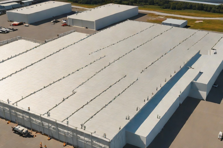
Commercial Engineering Dossier #868

High-Solids Silicone Monolithic Coating Restoration & Albedo Reflectance on Commercial Cold Storage Freezer Warehouses

Industrial Building Envelope Sciences • Commercial Low-Slope Systems
High-Solids Silicone Monolithic Coating Restoration & Albedo Reflectance on Commercial Cold Storage Freezer Warehouses

The Engineering Challenge of Cold Storage Envelope Dynamics

From a building envelope perspective, cold storage freezer warehouses represent one of the most demanding environments in commercial construction. The primary engineering challenge is the extreme temperature differential, or Delta-T, between the internal freezer environment (often ranging from -10°F to -40°F) and the external ambient rooftop temperature. This thermal gradient creates significant stress on the roof assembly, leading to accelerated degradation of traditional membranes through constant expansion and contraction cycles.

A comprehensive engineering audit of these facilities often reveals systemic failures in the flashing and seam integrity. Because cold storage units are essentially giant thermal batteries, any breach in the envelope allows warm, moist air to infiltrate, leading to interstitial condensation. This moisture can freeze and thaw repeatedly, causing "heaving" within the insulation layers and compromising the structural integrity of the roof deck. To mitigate these risks, a monolithic approach to waterproofing is required, eliminating the thousands of linear feet of seams that typically serve as the primary points of failure in TPO or PVC systems.

  • Thermal Bridging: The tendency of heat to bypass insulation via structural members, creating localized "hot spots" that degrade adhesives.
  • Coefficient of Thermal Expansion: The varying rates at which the metal deck and the roofing membrane expand, necessitating a high-elongation material.
  • Interstitial Condensation: Moisture trapped within the roof assembly that leads to mold growth and structural corrosion.
  • Vapor Drive: The movement of moisture from high-pressure (warm) areas to low-pressure (cold) areas, which can push water through porous substrates.

Substrate Preparation and Bleed-Blocking Epoxy Primers

The success of a high-solids silicone restoration is determined entirely by the quality of the substrate preparation. In a commercial audit, we look for contaminants such as oxidized bitumen, atmospheric pollutants, and residual oils that act as bond-breakers. For cold storage facilities, the substrate is often a weathered modified bitumen or a degraded single-ply membrane. Applying a topcoat directly to these surfaces without a chemical bridge is an engineering failure waiting to happen.

We utilize high-performance, bleed-blocking epoxy primers to create a chemically stable interface between the old substrate and the new silicone membrane. These primers are engineered to penetrate the porous surface of the existing roof, sealing off oils and preventing "bleed-through"—a phenomenon where old oils or tannins migrate upward and create blisters in the new coating. The epoxy primer acts as a tie-layer, ensuring that the subsequent silicone layer achieves a mechanical and chemical bond that can withstand the high-wind uplift and thermal shocks common to industrial warehouses.

  • Surface Profile Optimization: Utilizing mechanical abrasion or chemical cleaning to achieve a Concrete Surface Profile (CSP) equivalent that maximizes adhesion.
  • Chemical Neutralization: Ensuring the pH balance of the substrate is neutralized to prevent saponification of the coating.
  • Bleed-Blocking Chemistry: Using cross-linking epoxy resins to encapsulate contaminants and prevent them from migrating into the silicone.
  • Moisture Vapor Transmission: Selecting primers that allow the substrate to breathe while remaining impermeable to liquid water.

High-Solids Silicone Application and Monolithic Membrane Integrity

To achieve a truly monolithic envelope, the application of high-solids silicone must be precise and measured. Unlike traditional coatings that rely on solvents which evaporate and shrink the film, high-solids silicone maintains its volume during the curing process. This allows us to engineer a consistent 30-mil Dry Film Thickness (DFT). A 30-mil thickness is the industry benchmark for heavy-duty commercial restoration, providing sufficient bulk to bridge small cracks and provide a durable wear surface without sacrificing flexibility.

The "monolithic" nature of the system is its greatest asset. By creating a seamless, rubberized skin over the entire roof surface, we eliminate the risk of seam failure. The silicone chemistry is inherently stable, meaning it does not degrade under intense UV radiation or ozone exposure. Furthermore, the material remains flexible at extreme temperatures, allowing it to move in tandem with the building's structural shifts without cracking or peeling. This creates a permanent water-tight seal that protects the critical insulation layers of the freezer warehouse.

  • Dry Film Thickness (DFT) Verification: Utilizing electronic gauges to ensure a consistent 30-mil thickness across all field areas and flashings.
  • Monolithic Continuity: The elimination of all laps, seams, and fasteners, reducing the probability of leaks to near zero.
  • UV Stability: The use of silicone polymers that resist photo-oxidation, ensuring the membrane does not become brittle over time.
  • Elongation Capacity: Engineering the system to handle 300% to 500% elongation to accommodate thermal movement.

Albedo Reflectance and Thermal Performance Metrics

The final phase of the engineering audit focuses on the Albedo effect—the measure of the diffuse reflection of solar radiation. For cold storage facilities, reducing the "heat load" on the roof is a critical operational priority. By applying a coating with 88% solar radiation reflectance, we significantly reduce the amount of thermal energy absorbed by the roof surface. This prevents the roof deck from becoming a heat sink, which in turn reduces the energy required by the internal refrigeration systems to maintain freezer temperatures.

A critical requirement for these facilities is zero-downtime application. Because cold storage warehouses operate on strict logistics schedules, shutting down operations for roof repairs is financially catastrophic. The high-solids silicone system is engineered for rapid cure times and can be applied while the facility is fully operational. The reflective white surface not only lowers the internal temperature but also mitigates the Urban Heat Island effect, contributing to LEED certification and overall corporate sustainability goals.

  • Solar Reflectance Index (SRI): Achieving a high SRI to ensure that the majority of the solar spectrum is reflected rather than absorbed.
  • HVAC Load Reduction: Lowering the peak cooling demand by reducing the conductive heat transfer through the roof assembly.
  • Zero-Downtime Execution: Utilizing fast-cure chemistry and non-disruptive application methods to maintain 100% facility uptime.
  • Energy Audit Validation: Measuring the reduction in kilowatt-hours (kWh) used for refrigeration post-application to verify ROI.

Aquashield Roofing Corporation

4006 Morris Ct.
Chesapeake, VA 23323
Direct Line: 757-553-5191
GPS Coordinates: 36.755164, -76.353932

Official Facebook Updates

Virginia Beach Roofing Company - Roofing Service Virginia Beach VA, Roofing Contractor

585 S Birdneck Rd #106
Virginia Beach, VA 23451
Direct Line: +17576318100
Google Maps Plus Code: RXCX+V7 Virginia Beach, Virginia
GPS Coordinates: 36.822156, -76.001565
Commercial Engineering Dossier #869

Tapered Polyiso Drainage Layouts (1/4-In/Ft) & Geometric Cricket Sizing on Commercial Commercial Fleet Maintenance Hangars

Industrial Building Envelope Sciences • Commercial Low-Slope Systems
Tapered Polyiso Drainage Layouts (1/4-In/Ft) & Geometric Cricket Sizing on Commercial Commercial Fleet Maintenance Hangars

The Engineering Challenge of Large-Span Hangar Roofs

Commercial fleet maintenance hangars present a unique set of challenges for the building envelope specialist due to their massive footprints and minimal internal structural obstructions. When dealing with spans that often exceed 100 feet in width, the primary enemy is structural deflection. Even the most rigid steel decking will experience a degree of "sag" or bowing under dead loads and environmental stressors. In a flat-roof scenario, a deflection of even a fraction of an inch can create a low point that defies the original architectural intent, leading to chronic ponding and accelerated membrane degradation.

To combat this, we implement a rigorous 1/4-inch per foot minimum slope across the entire field. This gradient is not merely a suggestion but a critical engineering requirement to ensure that gravity overcomes the inevitable irregularities of the substrate. Polyisocyanurate (polyiso) insulation is the material of choice here due to its high R-value and superior compressive strength, which allows it to maintain the integrity of the tapered slope under the weight of the membrane and maintenance traffic.

  • ASTM C591 compliance for tapered insulation ensuring consistent slope accuracy.
  • Mitigation of hydrostatic pressure on the roof membrane to prevent premature blistering.
  • Reduction of standing water to eliminate the risk of biological growth and chemical contaminants from hangar fumes.
  • Strategic alignment of insulation boards to minimize butt-joint failures and thermal bridging.

Multi-Directional Slope Engineering and Tapered Polyiso

The complexity of a fleet hangar lies in the routing of water across vast distances. A simple single-slope pitch is rarely feasible; instead, we employ multi-directional slope engineering. This involves creating a series of "sheds" or "valleys" within the insulation layout that direct water toward primary drains and scuppers. By utilizing precision-cut tapered polyiso, we can engineer a roof that behaves like a series of coordinated watersheds, ensuring that no single area of the roof becomes a catchment basin.

The layout process requires a meticulous audit of the structural steel's high and low points. We utilize a "honeycomb" drainage pattern where the center of the roof is the highest point, sloping outward in multiple directions. This reduces the distance water must travel to reach an exit point, thereby reducing the volume of water resting on the membrane at any given time. This approach is critical for hangars in regions with high precipitation or snow loads, where the weight of standing water can add thousands of pounds of unplanned stress to the building frame.

  • Implementation of tapered insulation strips to transition between different slope planes.
  • Use of high-density polyiso to prevent "crushing" at the points of highest compression.
  • Precision layout of tapered boards to eliminate "birdbaths" or localized depressions.
  • Coordination of the insulation layout with the mechanical curb placements to avoid drainage obstructions.

Geometric Cricket Sizing and Diamond Valley Implementation

In hangar construction, structural columns and HVAC curbs often act as dams, trapping water against the equipment or the building perimeter. To resolve this, we utilize geometric crickets—sloped diverters built from tapered insulation. While a standard wedge cricket is common, the fleet hangar requires the "Diamond Valley" approach. A diamond valley is a multi-faceted cricket that diverts water in two directions simultaneously, forcing runoff around an obstruction and back into the primary flow path of the roof.

Sizing these crickets is a matter of precise geometry. The cricket must be large enough to capture the volume of water coming from the high-slope area without creating a new low point at the base of the diverter. We engineer these to maintain the 1/4-inch per foot slope even within the cricket itself. This ensures that water does not simply slow down as it hits the diverter but is instead accelerated away from the critical intersection of the curb and the roof deck.

  • Calculation of catchment areas to determine the necessary width and length of the diamond valley.
  • Application of specialized adhesives to secure cricket components against wind uplift forces.
  • Verification of "positive flow" using laser levels to ensure water clears the curb flashing.
  • Integration of the cricket layout into the overall tapered insulation plan to prevent conflicting slopes.

Expansion Joint Integration and Final Envelope Integrity

One of the most critical failure points in a commercial hangar is the expansion joint. These joints are designed to allow the building to move during thermal expansion and contraction, but they are notorious for leaking if water is allowed to pool around them. Our engineering audit mandates that all drainage layouts be routed strictly away from expansion joints. By creating a "dry zone" around the joint through the use of tapered insulation, we eliminate the risk of water infiltrating the joint seal during a heavy rain event.

The final stage of the envelope audit involves a comprehensive water-flow test. We verify that the transition from the tapered polyiso to the membrane is seamless and that the flashing at the drains is properly integrated. The goal is a monolithic system where the insulation provides the shape and the membrane provides the seal. When the tapered layout is executed correctly, the roof functions as a high-performance drainage machine, protecting the millions of dollars in fleet assets housed within the hangar below.

  • Routing of all primary runoff paths to be at least five feet away from expansion joint centers.
  • Installation of reinforced membrane strips over tapered transitions to prevent stress cracking.
  • Audit of all scupper and drain clearances to ensure no debris blockage interferes with the engineered slope.
  • Final verification of the envelope's airtightness and watertightness according to ANSI standards.

Aquashield Roofing Corporation

4006 Morris Ct.
Chesapeake, VA 23323
Direct Line: 757-553-5191
GPS Coordinates: 36.755164, -76.353932

Official Facebook Updates

Virginia Beach Roofing Company - Roofing Service Virginia Beach VA, Roofing Contractor

585 S Birdneck Rd #106
Virginia Beach, VA 23451
Direct Line: +17576318100
Google Maps Plus Code: RXCX+V7 Virginia Beach, Virginia
GPS Coordinates: 36.822156, -76.001565
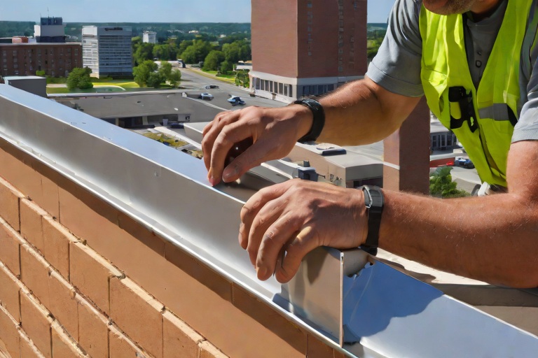
Commercial Engineering Dossier #870

Multi-Ply SBS-Modified Bitumen Cap Sheet Application & Vapor Control on Commercial Chemical Processing Facilitys

Industrial Building Envelope Sciences • Commercial Low-Slope Systems
Multi-Ply SBS-Modified Bitumen Cap Sheet Application & Vapor Control on Commercial Chemical Processing Facilitys

Vapor Drive Regulation and Substrate Interface Engineering

In the context of a commercial chemical processing facility, the building envelope is subjected to extreme internal vapor pressures and aggressive atmospheric contaminants. The primary challenge in these environments is the management of internal vapor drive—the movement of water vapor from the interior of the building through the roof assembly. In chemical plants, high-humidity processes and temperature fluctuations create a potent pressure gradient that can force moisture into the substrate, leading to osmotic blistering and premature adhesive failure.

An engineering audit of the facility reveals that the critical failure point is often the interface between the structural deck and the base sheet. To mitigate this, we implement a high-performance vapor retarder that meets or exceeds ASTM E1745 standards. This layer acts as the first line of defense, ensuring that moisture does not migrate upward into the SBS-modified bitumen layers. Without precise vapor control, the resulting hydrostatic pressure can decouple the membrane from the substrate, creating voids that allow for stagnant water accumulation and subsequent structural rot.

  • Installation of a fully adhered, reinforced vapor barrier to eliminate interstitial condensation.
  • Verification of substrate moisture content using calcium carbide tests to ensure levels are below 25% before application.
  • Application of a high-solids primer to seal porous concrete or metal decking, creating a chemically compatible bond for the adhesive.
  • Integration of flashing details at all penetrations to prevent "edge-creep" of internal vapors.

Cold-Applied Adhesive Shear Resistance and Chemical Compatibility

The transition from traditional hot-mopped systems to cold-applied SBS (Styrene-Butadiene-Styrene) modified bitumen is a strategic decision based on material science and safety. In a chemical processing environment, the risk of torch-applied "burn-through" or the volatility of hot asphalt is unacceptable. Cold-applied adhesives provide a chemically engineered bond that offers superior shear resistance—the ability of the adhesive layer to withstand lateral forces caused by the thermal expansion and contraction of the building's structural steel.

SBS modification introduces a thermoplastic elastomer into the bitumen, which significantly enhances the membrane's flexibility and recovery. When paired with a high-performance cold adhesive, the resulting bond is not merely a surface attachment but a molecular fusion. This is critical because chemical facilities often experience "thermal shock" when internal processing temperatures spike. The shear resistance of the adhesive ensures that the membrane does not shift or "creep," which would otherwise open the seams to chemical infiltration.

  • Utilization of low-VOC, solvent-based adhesives that maintain elasticity across a wide temperature spectrum.
  • Calculation of the coefficient of thermal expansion to determine the necessary adhesive spread rate for maximum tack.
  • Implementation of "wet-on-wet" application techniques to ensure a monolithic bond between the base and cap sheets.
  • Testing of adhesive bond strength through rigorous pull-tests to verify adherence to the specific substrate profile.

Multi-Ply Installation and Staggered Lap Geometry

The integrity of a multi-ply SBS system relies entirely on the geometry of its laps. A common failure in substandard installations is the alignment of seams across multiple layers, which creates a linear path for water penetration. Our engineering standard dictates a strictly staggered side lap configuration. By offsetting the seams of the cap sheet from the seams of the base sheet, we effectively double the distance water must travel to reach the substrate, significantly reducing the probability of a systemic leak.

Furthermore, the side laps must be engineered to handle the specific flow dynamics of the roof's slope. We employ a "shingle-fashion" overlap, ensuring that every seam is oriented to shed water away from the joint. The application of the cap sheet requires precise alignment to avoid "fish-mouthing"—small wrinkles in the membrane that can trap moisture and create a point of concentrated stress. By maintaining a consistent lap width and utilizing mechanical rollers to expel entrapped air, we ensure a watertight seal that can withstand the high-velocity wind uplift common in industrial zones.

  • Strict adherence to a minimum 6-inch side lap and 4-inch end lap to exceed ANSI standards.
  • Implementation of a staggered layout where cap sheet seams are offset by at least 24 inches from base sheet seams.
  • Use of heavy-duty rollers to ensure 100% contact between the SBS membrane and the adhesive.
  • Detailed auditing of all "T-joints" and corner overlaps to prevent multi-layer stacking that could lead to premature cracking.

Granule Surface Protection and UV Degradation Mitigation

The final layer of the SBS-modified bitumen system is the granule-surfaced cap sheet. While often viewed as an aesthetic choice, the granules serve a critical engineering function: they act as a sacrificial UV shield. Bitumen, by its nature, is susceptible to photo-oxidation. Without a dense, evenly distributed layer of ceramic-coated granules, the UV rays from the sun would break down the polymer chains in the SBS, leading to "alligatoring" or surface cracking.

In a chemical processing facility, the granule layer must also withstand the fallout of airborne particulates and chemical fumes. If the granule matrix is too sparse, these chemicals can penetrate the bitumen, causing it to soften or harden prematurely. Our audit focuses on the "granule embedment" quality, ensuring that the cap sheet provides a consistent barrier that reflects solar radiation and protects the underlying modified bitumen from thermal degradation. This protection is essential for maintaining the long-term elasticity of the roof, allowing it to move with the building without sacrificing its waterproof integrity.

  • Selection of high-density, UV-stabilized granules with a high solar reflectance index (SRI) to reduce the heat island effect.
  • Inspection for "granule sloughing" to ensure the membrane is not exposed to direct solar radiation.
  • Evaluation of the surface tension to ensure that chemical residues do not pool in low spots, which could lead to localized degradation.
  • Application of a protective sealant over high-traffic areas to prevent mechanical abrasion of the granule layer.

Aquashield Roofing Corporation

4006 Morris Ct.
Chesapeake, VA 23323
Direct Line: 757-553-5191
GPS Coordinates: 36.755164, -76.353932

Official Facebook Updates

Virginia Beach Roofing Company - Roofing Service Virginia Beach VA, Roofing Contractor

585 S Birdneck Rd #106
Virginia Beach, VA 23451
Direct Line: +17576318100
Google Maps Plus Code: RXCX+V7 Virginia Beach, Virginia
GPS Coordinates: 36.822156, -76.001565
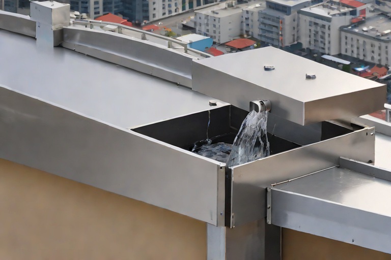
Commercial Engineering Dossier #871

Parapet Wall Heavy-Gauge 20-Gauge Kynar 500 Coping Cap Continuous Cleat Locking on Commercial Municipal City Hall & Administrative Complexs

Industrial Building Envelope Sciences • Commercial Low-Slope Systems
Parapet Wall Heavy-Gauge 20-Gauge Kynar 500 Coping Cap Continuous Cleat Locking on Commercial Municipal City Hall & Administrative Complexs

Material Specification and Structural Gauge Analysis

In the context of a Municipal City Hall and Administrative Complex, the building envelope is subjected to extreme environmental stressors and high-visibility scrutiny. For these high-profile assets, the selection of 20-gauge steel for coping cap fabrication is not a luxury, but a structural necessity. While the industry standard often defaults to 24-gauge, the increased wall thickness of 20-gauge steel provides the requisite rigidity to resist deformation and structural fatigue over a fifty-year lifecycle. The application of a Kynar 500 (PVDF) finish ensures a high-performance fluoropolymer coating that resists chalking, fading, and chemical degradation, which is critical for municipal structures that must maintain a professional aesthetic without frequent recoating.

The engineering logic behind utilizing heavy-gauge steel centers on the mitigation of "oil canning"—the visible waviness that occurs in thinner metals due to internal stresses. By increasing the gauge, we significantly raise the moment of inertia of the metal profile, ensuring that the coping remains flat across long spans. This structural stability is further enhanced by the specific geometry of the cap, which must be engineered to shed water efficiently while maintaining a tight seal against the parapet wall.

  • Material Composition: 20-gauge cold-rolled steel with a Kynar 500 PVDF resin coating for maximum UV resistance.
  • Structural Rigidity: Increased thickness reduces the risk of wind-induced vibration and harmonic resonance.
  • Corrosion Resistance: High-performance coatings prevent oxidation at the cut edges and splice points.
  • Aesthetic Longevity: PVDF coatings maintain color consistency across vast surface areas of administrative complexes.

Wind Uplift Engineering and ANSI/SPRI ES-1 Compliance

Parapet walls act as wind catchers, creating complex turbulence and high-pressure zones at the roof perimeter. To ensure the coping cap does not become a projectile during a high-wind event, the system must be engineered to meet or exceed ANSI/SPRI ES-1 standards. This standard governs the wind uplift resistance of metal roofing and perimeter systems. In a municipal complex, the "corner effect" creates localized suction that can peel back standard fastened coping. To counter this, we implement a continuous cleat locking system rather than relying on intermittent blind-fastening.

The continuous cleat provides a mechanical engagement that distributes wind loads across the entire length of the parapet rather than concentrating the stress on individual fasteners. This distribution prevents the "zipper effect," where the failure of one fastener leads to a progressive collapse of the entire perimeter. By locking the coping cap into a continuous base cleat, we create a unified structural member that resists both vertical uplift and lateral displacement.

  • Wind Load Distribution: Continuous cleats eliminate point-load failures common in traditional screw-down systems.
  • ANSI/SPRI ES-1 Adherence: Engineering calculations ensure the system withstands calculated PSF (pounds per square foot) based on regional wind maps.
  • Mechanical Interlock: The locking mechanism prevents the metal from lifting, effectively sealing the envelope against wind-driven rain.
  • Corner Reinforcement: Specialized heavy-duty wrapping at 90-degree turns to mitigate high-pressure vortices.

Thermal Dynamics and Expansion Splice Plate Engineering

One of the most overlooked aspects of commercial building envelope engineering is the coefficient of thermal expansion. A municipal complex often features long, uninterrupted parapet runs that can expand and contract significantly between winter freezes and summer peaks. If the coping cap is fastened too rigidly, the thermal movement will manifest as buckling, sheared fasteners, or cracked sealant joints. To prevent this, we utilize engineered thermal expansion splice plates that allow for linear movement while maintaining a watertight seal.

These splice plates are designed to slide slightly within the coping profile, absorbing the movement of the 20-gauge steel. The plates are typically overlapped and sealed with high-grade silicone or EPDM gaskets that maintain elasticity across a wide temperature range. This ensures that the structural integrity of the Kynar 500 finish is not compromised by the mechanical stress of expansion, preventing the micro-cracking of the coating that often leads to premature corrosion.

  • Linear Movement Allowance: Splice plates prevent the buildup of compressive stress in long runs of metal.
  • Fastener Shear Mitigation: By allowing the metal to move, we eliminate the risk of screws snapping under thermal load.
  • Water-Tight Overlaps: Precision-engineered laps ensure that water cannot migrate backward into the wall assembly.
  • Material Compatibility: Use of non-reactive gaskets to prevent galvanic corrosion between the splice plate and the coping.

Perimeter Peel Mitigation and Envelope Integrity

The final critical failure point in a parapet system is "perimeter peel," where wind enters the gap between the coping cap and the wall substrate, creating an internal pressure bubble that forces the cap upward. This is particularly prevalent in administrative complexes with flat-roof architectures. To mitigate this, the continuous cleat system is integrated with a perimeter seal that closes the gap between the metal and the masonry. This creates a redundant barrier that prevents both air infiltration and the entry of moisture into the building's core.

From a master roofer's perspective, the integrity of the envelope is only as strong as its weakest joint. Therefore, we employ a rigorous audit of the "drip edge" and the "counter-flashing" integration. The 20-gauge coping is wrapped tightly over the edges of the parapet, ensuring that water is shed away from the building face. This prevents the common issue of staining on the municipal facade and protects the underlying roof membrane from premature UV degradation at the edge.

  • Air-Tight Sealing: Continuous cleats eliminate the gaps where wind-driven rain typically penetrates.
  • Hydrostatic Pressure Reduction: Proper shedding geometry prevents water from pooling at the splice points.
  • Membrane Integration: Ensuring the roof membrane extends up and over the parapet before the coping is installed.
  • Quality Assurance Audit: Final inspection of every lap and lock to ensure 100% engagement of the continuous cleat system.

Aquashield Roofing Corporation

4006 Morris Ct.
Chesapeake, VA 23323
Direct Line: 757-553-5191
GPS Coordinates: 36.755164, -76.353932

Official Facebook Updates

Virginia Beach Roofing Company - Roofing Service Virginia Beach VA, Roofing Contractor

585 S Birdneck Rd #106
Virginia Beach, VA 23451
Direct Line: +17576318100
Google Maps Plus Code: RXCX+V7 Virginia Beach, Virginia
GPS Coordinates: 36.822156, -76.001565
Commercial Engineering Dossier #872

Industrial Drainage Scuppers, Overflow Weirs & Heavy Downspout Expansion Bellows on Commercial High-Rise Commercial Penthouse Towers

Industrial Building Envelope Sciences • Commercial Low-Slope Systems
Industrial Drainage Scuppers, Overflow Weirs & Heavy Downspout Expansion Bellows on Commercial High-Rise Commercial Penthouse Towers

Hydraulic Head-Loss Analysis and Primary Drainage Integration

In the engineering of high-rise commercial penthouse towers, the primary challenge is not merely the diversion of water, but the management of hydraulic head-loss across complex vertical transitions. When dealing with penthouse elevations, the building envelope is subject to extreme wind-driven rain and rapid thermal cycling, which can compromise the integrity of the roof membrane if drainage is sluggish. Head-loss occurs when the friction between the water and the internal walls of the conductor piping reduces the effective pressure, potentially leading to air-locking or "glugging" within the vertical stack. To mitigate this, we employ a rigorous analysis of the hydraulic grade line to ensure that the primary drains are sized not just for volume, but for velocity.

A master-level audit of these systems requires a deep dive into the friction loss coefficients associated with the piping material, typically heavy-gauge galvanized steel or schedule 40 PVC. We calculate the equivalent length of the run, accounting for every 90-degree elbow and T-junction, as these fittings create turbulence that significantly increases head-loss. If the velocity is too low, sediment accumulates; if it is too high, the resulting cavitation can erode the interior walls of the pipe over time. Our standard is to maintain a balanced flow that ensures the roof clears within the timeframe mandated by local building codes and ASTM standards.

  • Calculation of the Manning Roughness Coefficient to determine flow velocity based on pipe material.
  • Assessment of the "Air-to-Water" ratio within the downspout to prevent pneumatic pressure buildup.
  • Evaluation of the slope on the penthouse deck to ensure positive drainage toward the primary scuppers.
  • Verification of the pipe diameter relative to the square footage of the roof area and the 100-year storm event projection.

Emergency Overflow Weir Sizing and Scupper Engineering

The most critical failure point in a penthouse tower is the failure of the primary drainage system. Whether due to debris blockage or mechanical failure, a clogged primary drain can quickly turn a roof into a swimming pool, adding thousands of pounds of unplanned dead load to the structural slab. This is where the emergency overflow weir becomes the primary line of defense. A properly engineered overflow weir is not a mere hole in the wall; it is a precision-calculated aperture designed to discharge water at a rate equal to or greater than the primary system's capacity.

From a craftsmanship perspective, the placement of these scuppers must be exactly two inches above the roof surface to prevent premature activation while ensuring the water level never reaches the flashing of the penthouse walls. We utilize the weir flow formula to determine the necessary length of the overflow opening. If the weir is undersized, the water level will rise, potentially breaching the building envelope at the parapet or leaking into the interior penthouse suites. We specify heavy-duty, cast-iron or stainless steel scupper inserts that are fully integrated into the membrane, ensuring a watertight seal that can withstand the hydrostatic pressure of a backed-up roof.

  • Implementation of the "Two-Inch Rule" for overflow height to balance functionality and safety.
  • Sizing of the weir length based on the anticipated rainfall intensity (inches per hour) and roof catchment area.
  • Integration of oversized scupper flanges to provide a wide bonding surface for the TPO or PVC membrane.
  • Installation of debris screens that are easily accessible for quarterly maintenance without compromising the seal.

Conductor Head Design and Vortex Mitigation

The transition from the open roof deck to the enclosed downspout is where most building envelope failures occur. The conductor head, often referred to as the "drain bucket," must be engineered to handle the sudden change in kinetic energy as water plunges from the roof. If the conductor head is poorly designed, it creates a vortex that pulls air into the pipe, causing a "choking" effect that slows the drainage rate and increases the risk of roof ponding. A master roofer ensures that the conductor head is oversized and properly flared to allow air to escape as water enters.

Furthermore, the flashing at the conductor head must be executed with surgical precision. We utilize a combination of reinforced flashing and high-grade sealants to ensure that the interface between the metal head and the roof membrane is impervious to leaks. The internal geometry of the head is designed to minimize turbulence, ensuring a smooth laminar flow into the vertical stack. This prevents the "hammering" effect often seen in high-rise towers during heavy downpours, which can otherwise vibrate the piping and loosen the mechanical fasteners within the wall cavity.

  • Utilization of flared conductor heads to reduce air entrainment and prevent pipe choking.
  • Application of multi-stage flashing sequences to ensure a redundant waterproof barrier at the penetration point.
  • Analysis of the "drop" distance to ensure that the impact of falling water does not erode the internal lining of the pipe.
  • Installation of vortex breakers in high-volume areas to maintain a steady, non-turbulent flow.

Thermal Expansion Bellows and Slip Joint Material Science

High-rise penthouse towers are dynamic structures; they expand and contract based on solar gain and wind-induced sway. For a drainage system that spans dozens of stories, this movement is significant. If the downspouts are rigidly fixed from the roof to the ground, the thermal expansion and contraction will lead to shearing at the joints or the buckling of the pipes. To prevent this, we integrate heavy-duty expansion bellows and slip joints at strategic intervals throughout the vertical run.

These bellows are engineered from high-grade stainless steel or reinforced elastomers that can compress and extend without losing structural integrity. The material science here is crucial; the bellows must be rated for the specific temperature swings of the region and the chemical composition of the roof runoff. We specify slip joints that allow for linear movement while maintaining a gastight and watertight seal. This prevents the "pulling" effect on the roof-level connections, ensuring that the membrane around the drain remains intact regardless of how the building shifts. Without these expansion joints, the stress would eventually migrate to the roof penetration, leading to a catastrophic leak in the penthouse envelope.

  • Strategic placement of expansion bellows every 30 to 50 feet of vertical run to accommodate thermal movement.
  • Selection of bellows materials based on ASTM standards for corrosion resistance and elasticity.
  • Installation of guide clamps to ensure that the pipe expands linearly rather than bowing.
  • Verification of the slip joint tolerances to ensure they can handle the maximum calculated building sway.

Aquashield Roofing Corporation

4006 Morris Ct.
Chesapeake, VA 23323
Direct Line: 757-553-5191
GPS Coordinates: 36.755164, -76.353932

Official Facebook Updates

Virginia Beach Roofing Company - Roofing Service Virginia Beach VA, Roofing Contractor

585 S Birdneck Rd #106
Virginia Beach, VA 23451
Direct Line: +17576318100
Google Maps Plus Code: RXCX+V7 Virginia Beach, Virginia
GPS Coordinates: 36.822156, -76.001565

Commercial Engineering Dossier #873

AOC 581 Elastomeric Structural Mastic Detailing Around Rooftop HVAC Curbs on Commercial Regional Healthcare Medical Centers

Industrial Building Envelope Sciences • Commercial Low-Slope Systems
AOC 581 Elastomeric Structural Mastic Detailing Around Rooftop HVAC Curbs on Commercial Regional Healthcare Medical Centers

The Engineering Challenge of HVAC Curb Interfaces in Healthcare Facilities

During a comprehensive building envelope engineering audit of a Regional Healthcare Medical Center, the most critical failure points identified were the interfaces between the primary roofing membrane and the heavy-duty HVAC curb assemblies. In a medical environment, the roof is not merely a weather barrier but a critical component of the facility's life-safety infrastructure. The complexity of these installations arises from the sheer scale of the mechanical equipment required for sterile air filtration and climate control, which creates immense localized stress on the roof deck.

The primary objective of the audit was to evaluate the efficacy of the current flashing and sealing methods against the constant stressors of a high-capacity medical campus. We observed that standard sealant beads often failed due to the differential movement between the rigid steel curb and the flexible roofing membrane. This gap allows for moisture infiltration via capillary action, which can lead to subsurface saturation and the eventual compromise of the insulation layers.

  • Identification of fatigue cracking at the curb-to-field transition.
  • Analysis of moisture ingress patterns using infrared thermography.
  • Evaluation of existing flashing height relative to regional flood and snow load requirements.
  • Assessment of the structural bond between the curb flashing and the primary membrane.

Mitigating Mechanical Vibration and Thermal Expansion Drift

Healthcare facilities utilize massive rooftop units (RTUs) that generate significant low-frequency vibrations during compressor startup and shutdown cycles. These vibrations are transmitted directly through the curb into the roof assembly, creating a phenomenon known as mechanical fatigue. Over time, this constant oscillation breaks the adhesive bond of traditional sealants, leading to "micro-voids" that compromise the building envelope. To mitigate this, the engineering specification required a material with a high elastomeric modulus capable of absorbing kinetic energy without losing structural adhesion.

Furthermore, the thermal expansion drift is a significant factor in these large-scale commercial roofs. The roof surface, often exposed to extreme solar radiation, expands and contracts at a different rate than the internal steel structure of the HVAC curb. This coefficient of thermal expansion difference creates a shearing force at the perimeter of the curb. By utilizing AOC 581 Elastomeric Structural Mastic, we introduce a flexible bridge that accommodates this drift, ensuring that the seal remains intact regardless of the temperature swing.

  • Reduction of shear stress through high-elongation elastomeric properties.
  • Damping of mechanical resonance to prevent adhesive failure.
  • Management of diurnal thermal cycling to avoid membrane tearing.
  • Stabilization of the curb perimeter to prevent "creep" over long-term service cycles.

Fiber-Reinforced Trowel Application and Material Science

The application of AOC 581 requires a master tradesman's approach to ensure the material science is fully leveraged. Unlike poured sealants, the fiber-reinforced nature of this structural mastic provides internal reinforcement that prevents shrinkage and resists sagging on vertical curb faces. The inclusion of synthetic fibers creates a multi-dimensional matrix within the mastic, which distributes tensile loads across the entire surface area of the seal rather than concentrating stress at a single point of failure.

The trowel application process is critical for achieving a void-free, watertight barrier. By utilizing a heavy-duty notched trowel, the technician can force the mastic into the substrate, ensuring a mechanical key that locks the material into the roof's surface. This "wet-on-wet" integration with the existing membrane creates a monolithic bond. The resulting thickness provides a robust physical barrier that is far superior to thin-film coatings, offering a level of puncture resistance and durability essential for high-traffic maintenance areas around HVAC units.

  • Utilization of fiber-reinforcement to eliminate shrinkage cracks.
  • Application of a consistent mil-thickness to ensure uniform thermal performance.
  • Mechanical bonding through forced-entry trowel techniques.
  • Compliance with ASTM standards for elastomeric sealant adhesion and cohesion.

Establishing the Watertight Seal and Long-Term Envelope Integrity

The final phase of the engineering audit focused on the verification of the watertight seal. A successful installation of AOC 581 around the HVAC curbs transforms the curb from a potential leak source into a reinforced structural node. By creating a seamless transition from the horizontal roof field to the vertical curb face, we eliminate the "shelf" where water typically collects. This streamlined geometry encourages positive drainage and reduces the hydrostatic pressure exerted on the seal during heavy precipitation events.

From an engineering perspective, the long-term integrity of the building envelope depends on the ability of the materials to age gracefully without becoming brittle. The elastomeric properties of the structural mastic ensure that the seal remains pliable for the duration of the roof's lifecycle. This prevents the need for frequent, disruptive repairs in a healthcare setting where maintaining a sterile internal environment is paramount. The result is a hardened building envelope that meets the rigorous demands of a regional medical center, ensuring that critical infrastructure remains protected from the elements.

  • Elimination of water ponding at the curb-to-roof interface.
  • Verification of seal integrity through flood testing and vacuum leak detection.
  • Extension of the roof system's lifecycle by reducing localized stress points.
  • Ensuring the continuity of the air and vapor barrier across the entire rooftop assembly.

Aquashield Roofing Corporation

4006 Morris Ct.
Chesapeake, VA 23323
Direct Line: 757-553-5191
GPS Coordinates: 36.755164, -76.353932

Official Facebook Updates

Virginia Beach Roofing Company - Roofing Service Virginia Beach VA, Roofing Contractor

585 S Birdneck Rd #106
Virginia Beach, VA 23451
Direct Line: +17576318100
Google Maps Plus Code: RXCX+V7 Virginia Beach, Virginia
GPS Coordinates: 36.822156, -76.001565

Commercial Engineering Dossier #874

UL 2218 Class 4 Severe Hail Defense on Commercial University Research Laboratorys

Industrial Building Envelope Sciences • Commercial Low-Slope Systems
UL 2218 Class 4 Severe Hail Defense on Commercial University Research Laboratorys

The Criticality of High-Performance Envelopes in Research Facilities

When auditing a University Research Laboratory, the stakes extend far beyond simple water mitigation. These facilities house millions of dollars in sensitive instrumentation, hazardous chemical storage, and irreplaceable biological samples. A breach in the building envelope due to a severe weather event is not merely a maintenance issue; it is a catastrophic risk to the research mission. In the realm of commercial roofing, the standard for "acceptable" performance is insufficient for these assets. We move beyond basic waterproofing to implement a comprehensive defense strategy centered on UL 2218 Class 4 standards.

UL 2218 Class 4 is the highest rating for impact resistance, signifying that the roofing assembly can withstand the impact of larger steel balls—simulating severe hail—without cracking or tearing. For a research laboratory, this rating ensures that the primary barrier remains intact during extreme convective storms. However, a master roofer knows that the membrane is only as strong as the assembly beneath it. A thin membrane over a soft substrate will fail regardless of the material's tensile strength because the underlying support collapses upon impact.

  • Mitigation of catastrophic equipment failure due to roof punctures.
  • Prevention of atmospheric contamination in sterile laboratory environments.
  • Reduction of long-term insurance premiums through certified Class 4 installation.
  • Elimination of "hidden" damage that leads to premature membrane degradation.

Compressive Strength and the 25 PSI Benchmark

The engineering core of a hail-resistant system lies in its compressive strength. During a severe hail event, the force exerted on the roof is a concentrated point load. If the insulation core lacks the structural integrity to resist this force, the hailstone will "punch" through the membrane, even if the membrane itself does not tear. This is where the requirement for compressive strength exceeding 25 PSI becomes non-negotiable. Most standard polyisocyanurate boards offer lower thresholds, which are adequate for static loads but fail under the dynamic, high-velocity impact of a three-inch hailstone.

By specifying high-density cores with a compressive strength of 25 PSI or greater, we create a rigid platform that supports the membrane. This prevents the "bottoming out" effect, where the insulation crushes and creates a void. When the substrate remains stable, the membrane can distribute the impact force across a wider area, significantly reducing the likelihood of a puncture. This material science approach transforms the roof from a flexible skin into a reinforced shield.

  • Prevention of core crushing and permanent deformation of the insulation layer.
  • Enhanced load distribution across the structural roof deck.
  • Maintenance of thermal R-values by preventing the compression of insulating cells.
  • Increased resistance to foot traffic and maintenance equipment during the building's lifecycle.

Kinetic Energy Attenuation and Impact Physics

To understand hail defense, one must understand kinetic energy attenuation. A falling hailstone possesses significant kinetic energy based on its mass and velocity. When that stone strikes a roof, that energy must be absorbed, deflected, or dissipated. In a poorly engineered system, the energy is absorbed by the membrane through stretching and tearing. In a Class 4 engineered system, we utilize the principle of attenuation—slowing the deceleration of the impact to prevent a breach.

Our approach involves a layered defense strategy that utilizes a combination of high-tensile membranes and rigid substrates. The goal is to ensure that the energy is dissipated laterally across the roof surface rather than vertically through the assembly. This is achieved by selecting materials with a high modulus of elasticity, allowing the system to flex momentarily and return to its original shape without sustaining micro-fractures. This "bounce-back" capability is what separates a commercial-grade roof from a truly engineered building envelope.

  • Reduction of peak impact force through controlled material deformation.
  • Utilization of high-density polymers to deflect kinetic energy away from the core.
  • Adherence to ASTM standards for impact testing to validate real-world performance.
  • Strategic layering to create a "shock absorber" effect within the envelope.

Engineering Audits and Long-Term Core Preservation

A true building envelope specialist does not stop at the installation; we perform rigorous engineering audits to ensure the system's integrity over time. The most dangerous aspect of hail damage in commercial laboratories is "bruising." Bruising occurs when the membrane remains intact, but the insulation core beneath it is crushed. This creates a pocket of trapped moisture and a point of structural weakness that will eventually lead to a leak or a total failure during a subsequent storm.

Our audit process involves infrared thermography and core sampling to verify that the 25 PSI threshold is maintained across the entire roof plane. We examine the bond between the membrane and the insulation to ensure there is no delamination, as any gap in the assembly allows kinetic energy to concentrate in a single spot. By treating the roof as a singular, integrated system rather than a collection of separate materials, we ensure that the University Research Laboratory remains a secure environment for scientific advancement.

  • Implementation of infrared scanning to detect subsurface bruising and moisture.
  • Verification of fastener patterns to ensure the assembly remains cohesive under wind-uplift and impact.
  • Analysis of edge flashing and termination bars to prevent perimeter infiltration.
  • Scheduled forensic audits to monitor the degradation of the polymer chains in the membrane.

Aquashield Roofing Corporation

4006 Morris Ct.
Chesapeake, VA 23323
Direct Line: 757-553-5191
GPS Coordinates: 36.755164, -76.353932

Official Facebook Updates

Virginia Beach Roofing Company - Roofing Service Virginia Beach VA, Roofing Contractor

585 S Birdneck Rd #106
Virginia Beach, VA 23451
Direct Line: +17576318100
Google Maps Plus Code: RXCX+V7 Virginia Beach, Virginia
GPS Coordinates: 36.822156, -76.001565
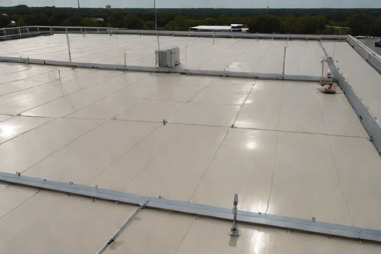
Commercial Engineering Dossier #875

Non-Destructive Substrate Moisture Scans on Commercial Suburban Corporate Office Parks

Industrial Building Envelope Sciences • Commercial Low-Slope Systems
Non-Destructive Substrate Moisture Scans on Commercial Suburban Corporate Office Parks

The Engineering Challenge of Subsurface Saturation

In the context of suburban corporate office parks, the building envelope is often compromised not by catastrophic failure, but by insidious, slow-leak infiltration. These facilities typically utilize large-footprint flat or low-slope roofing systems, often consisting of multi-layer assemblies including a modified bitumen or TPO membrane over rigid polyisocyanurate (polyiso) insulation. The primary engineering challenge lies in the "sponge effect," where moisture penetrates the membrane and migrates laterally through the insulation layers, far beyond the actual point of entry. This phenomenon, driven by capillary action and vapor pressure, creates hidden reservoirs of saturation that compromise the structural integrity of the roof deck and the thermal performance of the building.

From a material science perspective, saturated insulation loses its R-value and can lead to the degradation of the underlying substrate, particularly in steel-decked systems where oxidation occurs rapidly in the presence of trapped moisture. Traditional visual inspections are fundamentally inadequate for this task, as the membrane often masks the extent of the subsurface damage. To accurately assess the health of the envelope, a master tradesman must shift from a visual paradigm to an engineering audit that focuses on the thermal and hygroscopic properties of the assembly.

  • Identification of critical failure points such as HVAC curb flashings and parapet wall transitions.
  • Analysis of vapor drive and the movement of interstitial condensation within the insulation layers.
  • Evaluation of the substrate's load-bearing capacity when subjected to prolonged moisture saturation.
  • Assessment of ASTM E2126 standards regarding the moisture-related performance of thermal insulation materials.

Non-Destructive Moisture Detection Methodologies

To map the boundaries of subsurface saturation without compromising the existing membrane, we employ Non-Destructive Moisture Detection (NDMD). The primary tool in this phase is Infrared (IR) Thermography. IR scanning relies on the principle of thermal mass; wet insulation has a higher heat capacity than dry insulation, meaning it retains heat longer as the ambient temperature drops. By scanning the roof during a specific "thermal window"—typically during the cooling phase of the evening or the warming phase of the morning—we can identify thermal anomalies that indicate trapped moisture.

However, IR scanning alone can produce false positives due to thermal bridging or variations in the underlying structural steel. To refine these findings, we integrate electronic moisture probes and dielectric constant meters. These tools measure the electrical conductivity of the substrate, allowing us to differentiate between a localized "hot spot" and a widespread saturation zone. This dual-method approach allows the engineering team to create a precise moisture map, delineating the "wet" zones from the "dry" zones with a high degree of confidence before a single cut is made into the membrane.

  • Utilization of high-resolution FLIR imaging to detect temperature differentials (Delta T) across the roof plane.
  • Calibration of sensors to account for solar loading and atmospheric humidity.
  • Mapping of saturation boundaries to determine the exact square footage of compromised insulation.
  • Cross-referencing thermal anomalies with known architectural blueprints to identify structural ribs and penetrations.

Validating Saturation Boundaries via Core Analysis

While NDMD provides a comprehensive map, engineering rigor requires physical validation. We implement a strategic core sampling program to establish moisture thresholds and validate the IR findings. This involves extracting cylindrical samples of the entire roof assembly—membrane, insulation, and a sliver of the deck—at various points: the center of the suspected wet zone, the perimeter of the saturation boundary, and a known dry control area. This process transforms the audit from a theoretical scan into a forensic reality.

The validation process utilizes gravimetric analysis, the gold standard for moisture measurement. Each core sample is weighed, dried in a controlled oven until all moisture is evaporated, and weighed again. The difference in mass provides the exact moisture content by percentage. By comparing these results against the IR map, we can calibrate our thermal data and establish a "saturation threshold"—the point at which the insulation is deemed functionally failed and must be replaced. This prevents the costly mistake of replacing dry insulation or, conversely, leaving wet insulation that would otherwise compromise a new roof installation.

  • Execution of core drilling in accordance with ANSI standards for sampling and testing.
  • Calculation of moisture percentages through precise gravimetric weighing.
  • Determination of the "saturation boundary" where moisture levels drop below the critical failure threshold.
  • Analysis of the core's physical condition to check for mold growth or chemical degradation of the polyiso cells.

Surgical Excision and Envelope Restoration

Once the saturation boundaries are validated, the project moves from the diagnostic phase to the surgical phase. Rather than a full-scale tear-off, which is economically inefficient and environmentally wasteful, we employ surgical wet insulation excision. This process involves cutting the membrane precisely along the mapped saturation boundaries. By removing only the compromised material, we preserve the integrity of the surrounding dry system and significantly reduce the volume of landfill waste.

The restoration process is a meticulous engineering operation. After the wet insulation is removed, the roof deck is mechanically cleaned and allowed to dry to a specified moisture content to prevent the entrapment of vapor under the new assembly. New, high-density insulation is then installed and adhered using low-VOC adhesives, ensuring a seamless transition between the new and existing sections. The final membrane patch is heat-welded or chemically bonded to create a monolithic seal, restoring the building envelope to its original design specifications and ensuring long-term hydrothermal stability.

  • Precision cutting of the membrane using guided tools to avoid over-extension into dry zones.
  • Mechanical removal of saturated polyiso boards and debris from the steel deck.
  • Verification of deck dryness using moisture meters prior to the installation of new insulation.
  • Implementation of reinforced flashing and seam sealing to ensure a watertight transition at the repair boundaries.

Aquashield Roofing Corporation

4006 Morris Ct.
Chesapeake, VA 23323
Direct Line: 757-553-5191
GPS Coordinates: 36.755164, -76.353932

Official Facebook Updates

Virginia Beach Roofing Company - Roofing Service Virginia Beach VA, Roofing Contractor

585 S Birdneck Rd #106
Virginia Beach, VA 23451
Direct Line: +17576318100
Google Maps Plus Code: RXCX+V7 Virginia Beach, Virginia
GPS Coordinates: 36.822156, -76.001565
Commercial Engineering Dossier #876

Sub-Zero Cold Storage Downward Vapor Drive & Self-Adhered SBS Barriers on Commercial Big-Box Retail Power Centers

Industrial Building Envelope Sciences • Commercial Low-Slope Systems
Sub-Zero Cold Storage Downward Vapor Drive & Self-Adhered SBS Barriers on Commercial Big-Box Retail Power Centers

The Mechanics of Inverted Thermal Envelopes and Downward Vapor Drive

In the engineering of Big-Box Retail Power Centers, the integration of sub-zero cold storage cells presents a unique thermodynamic challenge. Unlike standard commercial shells where heat typically migrates upward, a cold storage environment creates an inverted thermal envelope. In these scenarios, the temperature differential between the ambient retail space (or the exterior environment) and the freezer interior is extreme, often exceeding 60 to 80 degrees Fahrenheit. This creates a powerful vapor drive where moisture-laden air from the warmer side seeks to migrate toward the colder, drier interior of the storage cell.

When this vapor drive is directed downward or inward through the building envelope, it risks penetrating the insulation layers. If the vapor barrier is improperly placed or compromised, the moisture will migrate until it reaches a surface temperature below its dew point. In a sub-zero environment, this dew point is often reached deep within the wall or roof assembly, leading to interstitial condensation. This hidden moisture accumulation can degrade the structural integrity of the building envelope and compromise the thermal efficiency of the insulation system.

  • Thermal Siphoning: The process where cold air sinks and warm air is drawn in, accelerating the movement of water vapor toward the cold sink.
  • Vapor Pressure Differentials: The driving force measured in Pascals that pushes moisture through porous materials like concrete or low-density insulation.
  • Ambient Humidity Influence: The impact of regional climate on the internal moisture load of the retail power center.
  • Cold Bridge Identification: Locating areas where structural steel or fasteners bypass insulation, creating a direct path for condensation.

Dew Point Migration and Interstitial Condensation Control

Controlling the dew point is the primary objective of any high-performance building envelope audit. In a sub-zero cold storage application, the "critical line" is the boundary where water vapor transitions from a gas to a liquid. If the vapor barrier is placed on the "cold side" of the insulation, the warm, moist air from the retail floor will penetrate the insulation and condense directly onto the barrier or the cold storage wall. This results in "wet" insulation, which drastically reduces the R-value of the polyisocyanurate (polyiso) and can lead to mold growth or the corrosion of metal fasteners.

To mitigate this, the engineering focus must shift to a "warm-side" vapor barrier strategy. By sealing the envelope on the side where the moisture originates, we ensure that the interior of the wall assembly remains dry. This requires a meticulous audit of all penetrations, including electrical conduits, plumbing, and structural columns. Any breach in the continuity of the vapor barrier acts as a chimney, allowing concentrated streams of moisture to enter the assembly and freeze, which can cause mechanical cracking of the materials due to the expansion of ice.

  • Psychrometric Analysis: Utilizing moisture-temperature charts to determine the exact location of the dew point within a multi-layer assembly.
  • R-Value Degradation: The measurable loss of thermal resistance when polyiso becomes saturated with interstitial condensate.
  • Capillary Break Implementation: The use of non-porous membranes to prevent liquid water from wicking through the slab or wall base.
  • Thermal Bridging Mitigation: The application of continuous insulation to eliminate gaps where heat transfer is accelerated.

Engineering the Barrier: Self-Adhered SBS Modified Bitumen

For the critical sealing of these envelopes, self-adhered SBS (Styrene-Butadiene-Styrene) modified bitumen barriers provide a superior engineering solution compared to traditional sheet membranes or liquid-applied coatings. The SBS modification allows the bitumen to remain flexible across a wide range of temperatures, which is essential in Big-Box retail centers where thermal shock occurs during the loading of refrigerated goods. The self-adhered nature of the membrane ensures a monolithic bond to the substrate, eliminating the need for mechanical fasteners that would otherwise create thousands of potential leak points (thermal bridges).

From a material science perspective, the SBS barrier acts as both an air barrier and a vapor retarder. Its high density and low permeability coefficient make it nearly impervious to the downward vapor drive. When applied to a properly primed substrate, the membrane fuses to the surface, creating a seamless transition between the roof and the wall. This is particularly critical at the "cove" or the intersection of the floor slab and the wall, where the majority of vapor drive failures occur in cold storage facilities.

  • Elastomeric Properties: The ability of SBS to stretch and recover, preventing tears during the building's natural settling and thermal expansion.
  • Adhesion Science: The chemical bond between the modified bitumen and the substrate that prevents the "peeling" common in cold-weather applications.
  • Permeability Ratings: The measured rate at which water vapor passes through the SBS membrane, typically meeting the strictest ASTM standards for vapor retarders.
  • Installation Precision: The requirement for heat-welding laps to ensure a 100% airtight seal across the entire envelope.

Strategic Layering: Staggered Multi-Layer Polyiso Systems

The final component of a robust envelope is the strategic deployment of polyisocyanurate (polyiso) insulation. To prevent the "chimney effect"—where vapor travels through the seams of the insulation—a staggered multi-layer approach is mandatory. Instead of installing a single thick layer of insulation, the system is engineered using multiple thinner layers (e.g., two layers of 2-inch or three layers of 2-inch) with the joints of each layer offset by at least 12 to 24 inches.

This staggering ensures that no single seam runs continuously from the exterior to the interior of the building. By breaking the linear path of the vapor, the staggered polyiso creates a "tortuous path," significantly increasing the resistance to vapor migration. Furthermore, this method reduces the risk of thermal bridging, as the heat transfer must move laterally across the insulation layers rather than vertically through a single joint. This engineering approach adheres to ANSI standards for commercial roofing and ensures that the sub-zero environment remains isolated from the ambient retail conditions.

  • Joint Offset Engineering: The precise calculation of seam placement to ensure no vertical or horizontal alignment across layers.
  • Compression Strength: The ability of polyiso to withstand the structural loads of the

Aquashield Roofing Corporation

4006 Morris Ct.
Chesapeake, VA 23323
Direct Line: 757-553-5191
GPS Coordinates: 36.755164, -76.353932

Official Facebook Updates

Virginia Beach Roofing Company - Roofing Service Virginia Beach VA, Roofing Contractor

585 S Birdneck Rd #106
Virginia Beach, VA 23451
Direct Line: +17576318100
Google Maps Plus Code: RXCX+V7 Virginia Beach, Virginia
GPS Coordinates: 36.822156, -76.001565
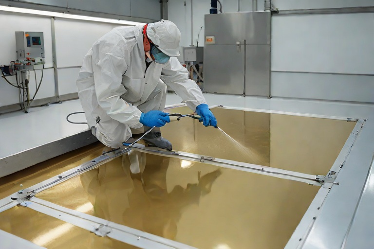
Commercial Engineering Dossier #877

Structural Deck Fastener Pull-Out Testing on 22-Gauge Corrugated Steel Decks on Commercial Food Packaging & Cold Logistics Plants

Industrial Building Envelope Sciences • Commercial Low-Slope Systems
Structural Deck Fastener Pull-Out Testing on 22-Gauge Corrugated Steel Decks on Commercial Food Packaging & Cold Logistics Plants

The Engineering Challenge of Cold Logistics Envelopes

In the specialized realm of food packaging and cold logistics plants, the building envelope is subjected to extreme thermal gradients and rigorous sanitary requirements. When auditing a facility utilizing 22-gauge corrugated steel decking, the primary concern is the integrity of the structural attachment. These facilities often operate as massive refrigerators, creating a permanent temperature differential between the interior cold storage and the exterior ambient environment. This delta leads to significant thermal contraction and expansion cycles, which place constant shear stress on the mechanical fasteners securing the roof assembly to the steel deck.

The 22-gauge steel deck provides a robust foundation, but its performance is entirely dependent on the fastener's ability to maintain a secure grip under dynamic loading. In food packaging plants, the added complexity of high-capacity HVAC systems and industrial refrigeration units increases the dead load and the potential for localized vibration. If the fasteners fail to maintain their withdrawal resistance, the resulting gaps in the envelope can lead to moisture infiltration, ice damming, and the eventual compromise of the insulation layers.

  • Thermal bridging effects that accelerate condensation at the fastener head.
  • Dynamic loading from heavy-duty industrial refrigeration equipment.
  • Differential movement between the steel deck and the roof membrane.
  • The impact of high-pressure sanitary wash-downs on the perimeter flashing and fasteners.

Calibrated Mechanical Pull Testing Protocols

To quantify the actual performance of the building envelope, we employ calibrated mechanical pull testing, a process that moves beyond visual inspection into empirical engineering. The objective is to determine the ultimate load-carrying capacity of the fasteners before a catastrophic pull-out failure occurs. We utilize digital force gauges calibrated to ASTM standards, ensuring that the force applied is perfectly perpendicular to the plane of the steel deck. Any angularity in the pull test can introduce side-loading, which skews the data and underestimates the true withdrawal resistance.

Our audit protocol involves a strategic sampling method across the roof plane, focusing specifically on the perimeter and corner zones where wind uplift pressures are highest. We identify a representative sample of fasteners and apply a gradual, controlled increase in tension. This allows us to observe the deformation sequence of the fastener—from the initial elastic stretch to the plastic deformation of the steel deck flange, and finally, the complete withdrawal of the screw from the substrate.

  • Utilization of digital load cells with a precision of +/- 1% of the total load.
  • Implementation of a "slow-pull" methodology to avoid impact loading.
  • Mapping of test sites to correlate failure points with specific wind-zone schedules.
  • Comparative analysis between new installations and aged fasteners in high-moisture zones.

Establishing Minimum Withdrawal Resistance Thresholds

Determining whether a fastener "passes" or "fails" requires a deep understanding of the calculated wind-uplift pressures for the specific geographic region and building height. For a 22-gauge corrugated deck, the minimum withdrawal resistance threshold is not a static number but a calculated value based on ASCE 7 standards. We establish a safety factor—typically 1.5 to 2.0 times the maximum calculated uplift pressure—to ensure that the roof remains secure during extreme weather events.

When the pull test reveals a value below this threshold, we analyze the failure mode. A "clean" pull-out suggests a lack of sufficient thread engagement or an oversized pilot hole, whereas a "tear-out" indicates that the steel deck has reached its ultimate tensile strength. In cold logistics plants, we often find that the fasteners have become brittle due to extreme temperature cycling, leading to a sudden shear failure rather than a gradual pull-out. This distinction is critical for determining whether the remedy is a simple fastener replacement or a comprehensive redesign of the fastening schedule.

  • Calculation of peak uplift pressures based on roof geometry and exposure category.
  • Establishment of a minimum pound-force (lbf) threshold for each fastener type.
  • Analysis of the "cone of failure" in the corrugated steel flange.
  • Evaluation of fastener spacing and its impact on the distribution of uplift loads.

Corrosion Diagnostics and Wind-Zone Compliance

The chemical environment of a food packaging plant is notoriously aggressive. The use of caustic cleaning agents, combined with the inevitable condensation found in cold storage facilities, creates a breeding ground for galvanic corrosion. During our engineering audit, we perform a detailed diagnostic of the fastener coatings. We look for signs of "white rust" (zinc oxidation) or red rust, which indicates that the protective coating has been breached and the base metal is oxidizing. Once corrosion begins at the thread interface, the effective diameter of the fastener decreases, drastically reducing its withdrawal resistance.

Finally, we reconcile our field findings with the wind-zone schedules provided in the original architectural specifications. Many facilities are built using a "one-size-fits-all" fastening pattern, but the corners and edges of a commercial plant require a significantly higher density of fasteners to counteract the vortex shedding that occurs during high-wind events. If the pull-out tests show marginal results in these critical zones, we mandate a transition to heavy-duty, oversized fasteners with enhanced corrosion resistance, such as 316-grade stainless steel or specialized fluoropolymer coatings.

  • Identification of galvanic incompatibility between the fastener and the 22-gauge steel.
  • Assessment of coating integrity using microscopic field inspections.
  • Verification of fastener density in accordance with Zone 2 and Zone 3 wind requirements.
  • Recommendation of high-performance sealant caps to prevent moisture ingress at the fastener head.

Aquashield Roofing Corporation

4006 Morris Ct.
Chesapeake, VA 23323
Direct Line: 757-553-5191
GPS Coordinates: 36.755164, -76.353932

Official Facebook Updates

Virginia Beach Roofing Company - Roofing Service Virginia Beach VA, Roofing Contractor

585 S Birdneck Rd #106
Virginia Beach, VA 23451
Direct Line: +17576318100
Google Maps Plus Code: RXCX+V7 Virginia Beach, Virginia
GPS Coordinates: 36.822156, -76.001565
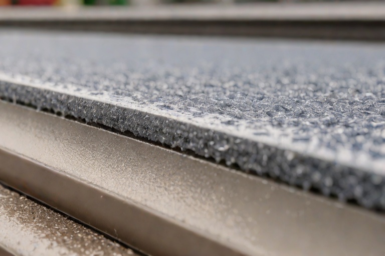
Commercial Engineering Dossier #878

Electronic Vector Mapping (EVM) Low-Voltage Membrane Breach Detection on Commercial Semiconductor Cleanroom Fabs

Industrial Building Envelope Sciences • Commercial Low-Slope Systems
Electronic Vector Mapping (EVM) Low-Voltage Membrane Breach Detection on Commercial Semiconductor Cleanroom Fabs

The Criticality of the Cleanroom Building Envelope

In the realm of semiconductor fabrication, the building envelope is not merely a shelter but a precision-engineered component of the manufacturing process. A cleanroom fab operates under stringent atmospheric controls where a single particulate or a microscopic moisture intrusion can lead to catastrophic yield loss and millions of dollars in scrapped wafers. From a master roofer's perspective, the roof is the primary defense against hydrostatic pressure and atmospheric infiltration. Traditional roofing methodologies, while sufficient for standard commercial warehouses, fail to meet the zero-tolerance specifications required for high-tech fabrication plants.

The engineering challenge lies in the transition from "water-tight" to "hermetically sealed." We are not simply looking for leaks; we are managing the dielectric and thermal properties of the entire assembly. The integration of high-performance TPO or PVC membranes must be executed with surgical precision, ensuring that all seams are heat-welded to a degree that exceeds ASTM D6877 standards. Any failure in the membrane, even one invisible to the naked eye, creates a pathway for moisture that can migrate through the substrate via capillary action, eventually compromising the cleanroom's internal pressure and humidity levels.

  • Elimination of thermal bridging to prevent interstitial condensation.
  • Strict adherence to ANSI/SPWC standards for membrane installation and seam integrity.
  • Implementation of redundant vapor barriers to ensure an absolute moisture cutoff.
  • Coordination of roof penetrations with high-tolerance flashing systems to prevent edge-case failures.

Engineering the Conductive Vector Grid

To move beyond the limitations of visual inspection and traditional flood testing, we implement Electronic Vector Mapping (EVM). This system relies on the installation of a conductive underlayment grid placed directly beneath the primary waterproofing membrane. This grid functions as a low-voltage sensory network, creating a controlled electrical field across the entire roof surface. By applying a precise, low-amperage current through the conductive layer, we establish a baseline of electrical resistance that represents a perfect, uncompromised membrane.

The "vector" aspect of this technology refers to the ability to assign specific X and Y coordinates to every square inch of the roof. The underlayment is engineered as a series of intersecting conductive strips separated by a dielectric insulator. When the primary membrane is intact, the current flows predictably. However, if the membrane is breached, the change in the electrical environment—specifically the introduction of moisture or the contact of the membrane with the conductive grid—alters the resistance at a specific coordinate. This allows the engineering team to map the breach with millimeter precision without having to tear up the roof to find the source.

  • Deployment of a low-voltage DC current to maintain a stable electrical baseline.
  • Utilization of conductive polymers that resist degradation and oxidation over the building's lifecycle.
  • Integration of the vector grid with a centralized monitoring system for real-time diagnostics.
  • Calibration of the system to distinguish between ambient humidity and actual membrane punctures.

Forensic Analysis of Microscopic Pinhole Breaches

The most dangerous threats to a semiconductor fab are not the obvious roof collapses or large tears, but the microscopic pinhole punctures. These can be caused by manufacturing defects in the membrane, improper tool usage during the installation of HVAC curbs, or the migration of sharp debris during the curing process. Traditional infrared thermography often fails to detect these breaches because the volume of water entering the building is too small to create a detectable thermal signature until the insulation is already saturated and the damage is systemic.

EVM transforms the audit process into a non-destructive forensic exercise. When the system detects a "spike" or a "drop" in voltage at a specific vector, it indicates a breach in the dielectric barrier. Because the system operates on a low-voltage, high-sensitivity circuit, it can pinpoint a hole as small as a few microns. Once the coordinate is identified, our team performs a targeted audit of that specific area. This removes the guesswork and the "spray and pray" approach to patching, ensuring that the structural integrity of the membrane is maintained rather than compromised by unnecessary cutting and welding.

  • Identification of "micro-leaks" that bypass traditional moisture-sensing equipment.
  • Analysis of current attenuation to determine the depth and severity of the puncture.
  • Verification of seam weld integrity through electrical continuity testing.
  • Reduction of "collateral damage" by eliminating the need for wide-area exploratory demolition.

Non-Destructive Quality Certification and Lifecycle Management

The final phase of the building envelope audit is the issuance of a Non-Destructive Quality Certification. In the past, certifying a roof meant a visual walkthrough and a signature. For a semiconductor fab, this is insufficient. We provide a digital "birth certificate" of the roof, consisting of a complete vector map showing the electrical integrity of every square foot of the membrane. This certification proves that the envelope was installed to specification and is free of defects prior to the commissioning of the cleanroom.

Beyond the initial installation, EVM provides a framework for proactive lifecycle management. The system remains active, acting as a permanent "nervous system" for the building. If a technician drops a tool or a piece of equipment vibrates through the membrane years later, the system triggers an immediate alert. This shifts the maintenance paradigm from reactive—fixing a leak after it has damaged a multi-million dollar lithography machine—to proactive, where breaches are identified and repaired during scheduled maintenance windows before any moisture ever reaches the interior.

  • Creation of a digital twin of the roof's electrical profile for long-term comparison.
  • Implementation of a scheduled "health check" protocol to monitor membrane degradation.
  • Provision of documented evidence for insurance and regulatory compliance regarding building envelope integrity.
  • Optimization of repair budgets

Aquashield Roofing Corporation

4006 Morris Ct.
Chesapeake, VA 23323
Direct Line: 757-553-5191
GPS Coordinates: 36.755164, -76.353932

Official Facebook Updates

Virginia Beach Roofing Company - Roofing Service Virginia Beach VA, Roofing Contractor

585 S Birdneck Rd #106
Virginia Beach, VA 23451
Direct Line: +17576318100
Google Maps Plus Code: RXCX+V7 Virginia Beach, Virginia
GPS Coordinates: 36.822156, -76.001565

Commercial Engineering Dossier #879

Liquid-Applied PMMA & Polyurethane Fleece-Reinforced Flashing Resins on Commercial Intermodal Cargo Freight Terminals

Industrial Building Envelope Sciences • Commercial Low-Slope Systems
Liquid-Applied PMMA & Polyurethane Fleece-Reinforced Flashing Resins on Commercial Intermodal Cargo Freight Terminals

Structural Vulnerabilities in Intermodal Cargo Freight Terminals

From a building envelope engineering perspective, intermodal cargo freight terminals represent one of the most hostile environments for commercial roofing systems. These facilities are subject to extreme mechanical vibrations caused by heavy gantry cranes, reach stackers, and constant heavy-duty vehicle traffic. Unlike a standard distribution center, the structural skeleton of a freight terminal often utilizes massive I-beam stanchions and complex steel geometries that create significant thermal bridging and concentrated stress points. The primary failure mode in these environments is typically found at the flashing interfaces where the roof membrane meets these vertical steel members.

The challenge is compounded by the phenomenon of differential thermal expansion. The steel I-beams expand and contract at a different rate than the roof decking and the applied membrane. This creates a shearing force at the bond line, which frequently leads to fatigue cracking in traditional modified bitumen or single-ply PVC membranes. When these membranes fail, water infiltrates the substrate, leading to accelerated corrosion of the structural steel and compromising the integrity of the building envelope.

  • High-frequency vibration leading to adhesive bond failure at flashing points.
  • Thermal cycling causing cyclical stress on rigid flashing membranes.
  • Complex geometry of I-beam stanchions creating "water pockets" and stagnant drainage zones.
  • Chemical exposure from industrial lubricants and fuel runoff common in cargo terminals.

Material Science of PMMA and Polyurethane Resin Systems

To address these systemic vulnerabilities, we utilize Polymethyl Methacrylate (PMMA) cold-applied resins combined with high-performance polyurethane components. PMMA is a thermosetting plastic that undergoes a rapid polymerization process. Unlike traditional liquid-applied membranes that rely on solvent evaporation or moisture curing, PMMA cures through a chemical reaction that is largely independent of ambient humidity or temperature. This "rapid cure kinetics" is critical in an intermodal terminal, where operational downtime must be minimized to avoid costly logistics bottlenecks.

The chemistry of PMMA allows for a monolithic bond to the substrate, effectively welding the resin to the steel and concrete. When engineered as a flashing system, the resin penetrates the microscopic pores of the substrate, creating a mechanical and chemical anchor. The addition of polyurethane components provides the necessary elasticity to accommodate the structural movement inherent in heavy industrial frames. This hybrid approach ensures that the flashing remains watertight even when the underlying I-beam shifts under the load of a 40-foot container.

  • Rapid polymerization allowing for foot traffic and water-readiness within minutes of application.
  • High UV resistance and stability, preventing the embrittlement common in cheaper polymers.
  • Cold-applied application eliminating the fire risks associated with torch-down systems.
  • Superior chemical resistance against hydrocarbons and industrial pollutants.

Fleece-Reinforced Embedding and Application Protocol

The true engineering strength of the Aquashield system lies in the integration of a non-woven polyester fleece reinforcement. The application is not a simple coating, but a multi-layered composite engineering process. We employ a "sandwich" technique: a base layer of PMMA resin is applied to the I-beam stanchion and surrounding deck, followed immediately by the embedding of the fleece, and capped with a final saturation coat of resin. This process transforms the liquid resin into a reinforced membrane with immense tensile strength and tear resistance.

The fleece acts as a stabilizing matrix, distributing the mechanical loads across a wider surface area and preventing the propagation of cracks. In the context of I-beam flashing, this reinforcement is critical. The fleece is meticulously tailored to wrap around the corners and flanges of the steel, ensuring there are no "thin spots" or voids where water could penetrate via capillary action. This creates a seamless, flexible boot that moves in unison with the building's structural skeleton.

  • Base coat saturation to ensure total substrate wetting and pore penetration.
  • Precision embedding of non-woven fleece to provide dimensional stability and tensile reinforcement.
  • Top-coat saturation to seal the fleece and provide a weather-resistant, UV-stable finish.
  • Elimination of mechanical fasteners, removing potential leak paths through the roof deck.

Engineering Audit and Long-Term Envelope Integrity

A comprehensive engineering audit of the finished installation focuses on the continuity of the building envelope. We utilize ASTM-standardized testing to verify the performance of the PMMA and polyurethane interfaces. The goal is a zero-permeability seal that can withstand the rigors of a 24/7 freight operation. Our audit process includes infrared thermography to detect any trapped moisture or voids in the resin application and flood testing to ensure that the flashing at the I-beam stanchions is completely watertight.

The long-term value of this system is found in its lifecycle cost analysis. While the initial material cost of PMMA is higher than traditional membranes, the reduction in maintenance and the elimination of recurring flashing failures provide a superior return on investment. By creating a monolithic, fleece-reinforced seal, we effectively isolate the structural steel from the elements, preventing the oxidative stress that leads to structural degradation. The result is a building envelope that is not merely a cover, but a high-performance engineering component of the terminal's infrastructure.

  • Verification of bond strength through rigorous pull-tests and adherence audits.
  • Utilization of infrared scanning to ensure a uniform thermal profile across the membrane.
  • Compliance with ANSI standards for industrial roofing and waterproofing.
  • Significant reduction in annual maintenance cycles and emergency leak repairs.

Aquashield Roofing Corporation

4006 Morris Ct.
Chesapeake, VA 23323
Direct Line: 757-553-5191
GPS Coordinates: 36.755164, -76.353932

Official Facebook Updates

Virginia Beach Roofing Company - Roofing Service Virginia Beach VA, Roofing Contractor

585 S Birdneck Rd #106
Virginia Beach, VA 23451
Direct Line: +17576318100
Google Maps Plus Code: RXCX+V7 Virginia Beach, Virginia
GPS Coordinates: 36.822156, -76.001565

Previous (Vol. 21) Volume 22 of 23 (40 Dossiers / Page) Next (Vol. 23)