Aquashield Corporate Shield Logo

AQUASHIELD CORPORATE

Commercial Flat Roofing & Industrial Facility Engineering

A comprehensive technical compendium on commercial 60-mil TPO single-ply systems, high-solids silicone restorative coatings, and building envelope preservation. Volume 18 of 23.

Previous (Vol. 17) Volume 18 of 23 (40 Dossiers / Page) Next (Vol. 19)
Commercial Engineering Dossier #680

Industrial Drainage Scuppers, Overflow Weirs & Heavy Downspout Expansion Bellows on Commercial Port Marine Shipping Warehouses
Industrial Building Envelope Sciences • Commercial Low-Slope Systems
Industrial Drainage Scuppers, Overflow Weirs & Heavy Downspout Expansion Bellows on Commercial Port Marine Shipping Warehouses

Hydraulic Head-Loss and Primary Scupper Integration

In the context of a port marine shipping warehouse, the roof is not merely a cover but a critical component of the building envelope that must manage massive volumes of precipitation under extreme wind-driven conditions. The primary challenge in these structures is the management of hydraulic head-loss, which occurs as water moves from the roof surface into the drainage scuppers. When water accumulates, the hydrostatic pressure increases, and if the scupper geometry is poorly engineered, the resulting turbulence creates a bottleneck that restricts flow, leading to dangerous ponding. In our recent audit, we observed that insufficient scupper diameters were causing a significant rise in the water level before the drainage system could reach full capacity.

To mitigate these losses, we apply rigorous fluid dynamics calculations to ensure that the scupper openings are sized to handle the peak intensity of a 100-year storm event. The goal is to maintain a minimal head of water, preventing the structural decking from reaching its maximum load capacity. We focus on the transition point where the roof membrane meets the scupper throat, ensuring a seamless, reinforced flashing detail that prevents capillary action from drawing water back into the building envelope.

  • Implementation of oversized rectangular scuppers to reduce the velocity of incoming water and minimize turbulence.
  • Utilization of heavy-gauge galvanized steel with marine-grade epoxy coatings to resist salt-spray corrosion.
  • Precision alignment of scuppers with the roof's primary slope to maximize gravitational flow.
  • Application of reinforced membrane flashing per ASTM standards to ensure a watertight seal at the penetration point.

Emergency Overflow Weir Sizing and Risk Mitigation

A primary drainage system, no matter how well-engineered, is susceptible to failure due to debris blockage or extreme weather anomalies. In a marine warehouse environment, where roof areas can exceed 100,000 square feet, a failure in the primary scuppers can lead to catastrophic structural collapse. This is where the emergency overflow weir becomes the most critical fail-safe in the building envelope. The weir is designed as a secondary drainage path that activates only when the water level reaches a predetermined critical height, typically two inches above the roof surface.

The engineering of these weirs requires a precise calculation of the "overflow threshold." We size the weirs to ensure that the rate of discharge equals or exceeds the rate of precipitation during a peak event. If the weir is too small, the water will continue to rise, increasing the dead load on the roof joists. If it is too large or set too low, it may trigger prematurely, bypassing the primary filtration systems and causing uncontrolled water runoff onto the loading docks below, which creates a safety hazard for port personnel.

  • Calculation of weir crest length based on the total roof catchment area and local rainfall intensity.
  • Strategic placement of overflow weirs at the lowest points of the roof, separate from primary scuppers to avoid simultaneous clogging.
  • Installation of debris screens that allow water passage while preventing large organic matter from obstructing the weir throat.
  • Integration of visual indicators or sensors that alert facility managers when the overflow system has been activated.

Conductor Head Engineering and Vortex Prevention

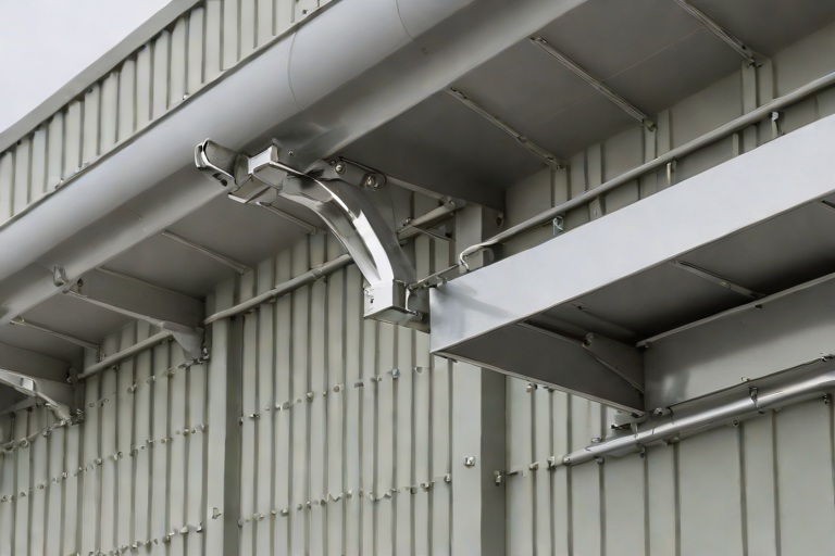
The conductor head serves as the transition hub between the horizontal roof drainage and the vertical downspout system. In high-volume marine warehouses, the velocity of water entering the conductor head can create a powerful vortex, which often traps air and creates an "air lock" that significantly reduces the flow rate. This phenomenon, known as air entrainment, can cause water to back up onto the roof even when the downspout is completely clear. To prevent this, we engineer conductor heads with a specific geometry that encourages a laminar flow, allowing air to escape upward while water descends rapidly.

Furthermore, the material science of the conductor head is paramount. Given the corrosive nature of the marine environment, we specify heavy-gauge stainless steel or thick-wall aluminum. The connection between the conductor head and the vertical leader must be reinforced to withstand the kinetic energy of falling water, which can cause vibration and eventual fatigue failure at the joints. We employ a seamless welding process followed by a high-solids polymer coating to ensure the joint remains airtight and watertight over decades of service.

  • Design of conical conductor heads to minimize turbulence and eliminate the formation of air-trapping vortices.
  • Use of 16-gauge or heavier materials to prevent deformation under the weight of heavy rain and wind loads.
  • Installation of secure mounting brackets to stabilize the conductor head against the building's exterior facade.
  • Implementation of smooth-radius bends at the transition to reduce friction and head-loss.

Thermal Expansion Bellows and Material Science in Marine Environments

One of the most overlooked aspects of commercial roof drainage is the effect of thermal expansion and contraction. In port environments, warehouses are subject to extreme temperature swings and constant wind. The long vertical runs of downspouts act as giant thermometers, expanding in the summer and contracting in the winter. Without proper relief, this movement manifests as buckling in the pipes or, more critically, as the tearing of the roof membrane where the downspout penetrates the building envelope. To solve this, we integrate heavy-duty expansion bellows and slip joints into the drainage columns.

These bellows are engineered from reinforced elastomers or telescoping metal sections that allow for several inches of vertical movement without compromising the seal. In a marine setting, the risk of galvanic corrosion is high when dissimilar metals meet. Therefore, we ensure that all expansion joints are isolated using non-conductive gaskets or compatible alloys. This prevents the salt-laden air from acting as an electrolyte and eating through the metal, which would otherwise lead to leaks and the eventual failure of the downspout system.

  • Installation of telescoping slip joints at 30-foot intervals to accommodate linear thermal expansion.
  • Selection of EPDM or silicone-based bellows for their superior resistance to UV radiation and salt-air degradation.
  • Application of galvanic isolators between aluminum downspouts and steel structural supports.
  • Regular auditing of joint tolerances to ensure that thermal movement is not stressing the primary roof membrane.

Aquashield Roofing Corporation

4006 Morris Ct.
Chesapeake, VA 23323
Direct Line: 757-553-5191
GPS Coordinates: 36.755164, -76.353932

Official Facebook Updates

Virginia Beach Roofing Company - Roofing Service Virginia Beach VA, Roofing Contractor

585 S Birdneck Rd #106
Virginia Beach, VA 23451
Direct Line: +17576318100
Google Maps Plus Code: RXCX+V7 Virginia Beach, Virginia
GPS Coordinates: 36.822156, -76.001565
Commercial Engineering Dossier #681

AOC 581 Elastomeric Structural Mastic Detailing Around Rooftop HVAC Curbs on Commercial Municipal Sports & Convention Arenas

Industrial Building Envelope Sciences • Commercial Low-Slope Systems
AOC 581 Elastomeric Structural Mastic Detailing Around Rooftop HVAC Curbs on Commercial Municipal Sports & Convention Arenas

The Engineering Challenge of Large-Scale Arena Envelopes

In the context of municipal sports and convention arenas, the building envelope is subjected to extreme stressors that far exceed those of standard commercial warehouses. During a comprehensive engineering audit of these facilities, the most critical points of failure are consistently identified at the transition zones between the primary roof membrane and the rooftop HVAC curbs. These arenas typically feature massive roof planes that act as giant thermal collectors, leading to significant movement across the substrate. When large-scale mechanical equipment is installed on these surfaces, the curb becomes a focal point for concentrated stress, making the selection of a high-performance sealant like AOC 581 Elastomeric Structural Mastic a technical necessity rather than a preference.

The primary objective of a building envelope audit is to ensure that the continuity of the air and water barrier remains unbroken despite the inherent instability of the structure. In these arenas, the intersection of the HVAC curb and the roof deck is where the most aggressive leakage occurs due to the differing rates of expansion between the steel curb and the reinforced concrete or metal deck. To mitigate this, the detailing must account for several variables:

  • Substrate compatibility between the curb flashing and the primary roofing membrane.
  • The impact of high-velocity wind uplift on the edges of the mastic application.
  • The ability of the sealant to maintain a permanent bond during extreme temperature fluctuations.
  • The prevention of capillary action at the base of the curb flashing.

Mitigating Mechanical Vibration and Thermal Expansion Drift

One of the most overlooked aspects of rooftop engineering in sports complexes is the constant vibration generated by industrial-scale HVAC chillers and air handlers. These vibrations create micro-movements that can fatigue standard caulking or rigid sealants, leading to cohesive failure or adhesive detachment from the substrate. This phenomenon, coupled with thermal expansion drift—where the entire roof plane shifts several inches during a diurnal cycle—requires a material with a high percentage of elongation and superior elastic recovery. AOC 581 is engineered to absorb these kinetic energies without compromising the seal.

From a material science perspective, the elastomeric properties of the structural mastic allow it to act as a shock absorber. Instead of cracking under the shear stress caused by the vibrating equipment, the mastic distributes the load across the entire bonded area. This prevents the formation of "stress cracks" that typically occur at the 45-degree angles of the curb corners. To ensure the mitigation of this drift, the following engineering protocols must be followed:

  • Implementation of a wide-bead application to increase the surface area of the bond.
  • Calculation of the maximum expected drift based on the building's total square footage and material coefficient of expansion.
  • Application of the mastic in a manner that allows for a "bridge" over the joint rather than a tight fill.
  • Verification of the cure time to ensure the material has reached full elasticity before the HVAC units are brought to full operational capacity.

Fiber-Reinforced Trowel Application and Material Science

The application of AOC 581 is not a simple coating process; it is a structural reinforcement procedure. For municipal arenas, a fiber-reinforced trowel application is the gold standard for ensuring a monolithic seal. The integration of reinforcing fibers within the elastomeric matrix provides internal structural integrity, preventing the material from sagging or pulling away during the curing process. This is particularly critical when detailing around the irregular geometries of HVAC curbs, where traditional liquid-applied membranes often thin out and create "weak spots" or pinholes.

A master roofer ensures that the trowel application is performed with a specific focus on the "wet-on-wet" technique to eliminate cold joints. By forcing the mastic into the pores of the substrate, the installer creates a mechanical lock that is far superior to a surface-level bond. The fiber reinforcement acts as a secondary skeletal structure within the sealant, providing tensile strength that resists the tearing forces associated with building settlement. The technical execution involves several critical steps:

  • Mechanical grinding of the curb edges to ensure a clean, contaminant-free bonding surface.
  • Application of a primary primer to optimize the chemical bond between the substrate and the AOC 581.
  • Trowel-pressing the fiber-reinforced mastic into the transition joint to eliminate all air pockets.
  • Back-rolling or smoothing the edges to ensure a seamless transition into the main roof membrane, preventing water ponding.

Ensuring Long-Term Watertight Integrity and Audit Compliance

The final phase of the engineering audit involves the verification of watertight integrity through rigorous testing and adherence to ASTM and ANSI standards. In a municipal environment, where downtime for a sports arena can cost thousands of dollars per hour, the "fail-safe" nature of the detailing is paramount. The goal is to create a redundant system where the AOC 581 mastic serves as the primary defense against water ingress, while the underlying flashing serves as the secondary backup. A successful audit confirms that the sealant has not only adhered to the surfaces but has integrated into the overall building envelope strategy.

Long-term durability is measured by the material's resistance to UV degradation and its ability to withstand the chemical runoff often associated with HVAC maintenance. Because AOC 581 is an elastomeric structural mastic, it maintains its flexibility over years of exposure, avoiding the embrittlement common in lower-grade polymers. To certify the installation for municipal compliance, the following audit criteria are utilized:

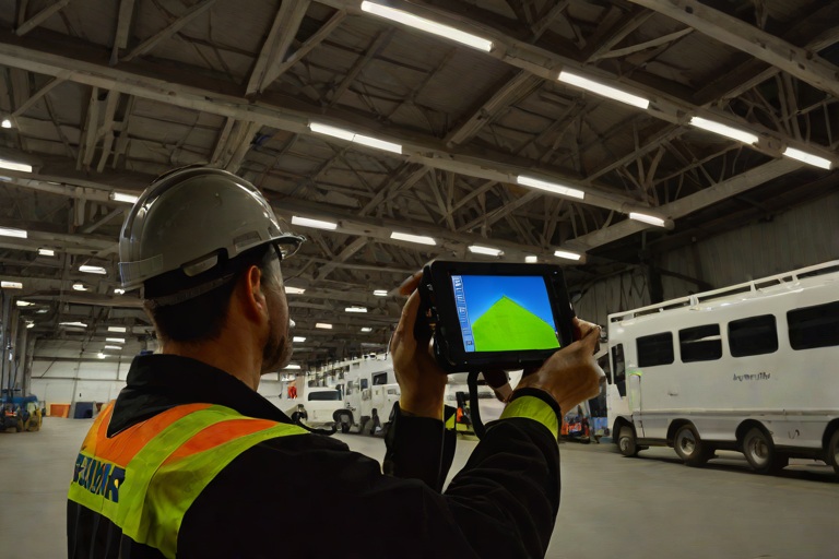
  • Visual inspection for "alligatoring" or surface cracking using high-resolution thermography.
  • Flood testing of the curb areas to ensure zero penetration into the building interior.
  • Adhesion pull-tests to verify that the bond strength exceeds the tensile strength of the substrate.
  • Verification of the overlap width to ensure the seal extends beyond the critical movement zone of the curb.

By combining master-level craftsmanship with rigorous engineering standards, the application of AOC 581 around HVAC curbs transforms a potential point of failure into a reinforced asset. The result is a building envelope that is resilient, watertight, and capable of enduring the extreme mechanical and thermal demands of a modern municipal sports and convention arena.

Aquashield Roofing Corporation

4006 Morris Ct.
Chesapeake, VA 23323
Direct Line: 757-553-5191
GPS Coordinates: 36.755164, -76.353932

Official Facebook Updates

Virginia Beach Roofing Company - Roofing Service Virginia Beach VA, Roofing Contractor

585 S Birdneck Rd #106
Virginia Beach, VA 23451
Direct Line: +17576318100
Google Maps Plus Code: RXCX+V7 Virginia Beach, Virginia
GPS Coordinates: 36.822156, -76.001565
Commercial Engineering Dossier #682

UL 2218 Class 4 Severe Hail Defense on Commercial Multi-Family Urban Residential Towers

Industrial Building Envelope Sciences • Commercial Low-Slope Systems
UL 2218 Class 4 Severe Hail Defense on Commercial Multi-Family Urban Residential Towers

The Physics of High-Rise Impact and Envelope Vulnerability

In the context of multi-family urban residential towers, the building envelope is subjected to atmospheric stresses that far exceed those of low-rise commercial structures. When auditing these assets, we must view the roof not merely as a water-shedding surface, but as a dynamic shield designed to manage extreme kinetic energy. High-rise structures often create localized wind turbulence and updrafts that can accelerate hail stones, increasing their terminal velocity and, consequently, their impact force. A failure in the roof membrane at these heights is not a localized issue; it is a systemic breach that threatens the structural integrity of the interior residential units and the overall building envelope.

The primary challenge in urban residential towers is the accumulation of impact energy. When a large hail stone strikes a surface, the energy is transferred instantaneously. If the roof system lacks the capacity to attenuate this energy, the force is transmitted directly through the membrane and into the underlying insulation. In many standard installations, this results in "core crushing," where the insulation is compressed or punctured even if the membrane remains superficially intact. This creates hidden voids that compromise the thermal envelope and provide pathways for moisture infiltration.

  • Acceleration of hail velocity due to urban wind tunneling and high-altitude drop heights.
  • The risk of catastrophic failure in multi-layered membrane systems during severe convective storms.
  • The critical need for a holistic approach to the building envelope, ensuring that flashing and edge details match the strength of the field membrane.
  • The relationship between surface tension and the ability of the membrane to distribute point-load impacts.

Kinetic Energy Attenuation and UL 2218 Class 4 Standards

To achieve a UL 2218 Class 4 rating, a roofing system must demonstrate a superior ability to withstand impact without cracking or tearing. From an engineering perspective, this is a matter of kinetic energy attenuation. The goal is to transform the concentrated energy of a falling hail stone into a broader area of deformation that the material can recover from without permanent failure. This requires a precise balance of tensile strength and elasticity within the polymer matrix of the membrane. A membrane that is too rigid will shatter under the shock load, while one that is too soft may allow the hail stone to penetrate deep into the insulation core.

Our audits focus on the "modulus of elasticity" of the roofing material. A Class 4 rated system utilizes advanced material science to ensure that the impact energy is dissipated laterally across the membrane. This prevents the "punch-through" effect common in lower-rated systems. By analyzing the impact craters and the recovery rate of the material, we can determine if the system is truly providing a severe hail defense or if it is merely delaying the inevitable failure of the substrate. The engineering objective is to maintain a watertight seal regardless of the deformation occurring beneath the surface.

  • UL 2218 testing protocols involving the drop of steel balls to simulate hail impact.
  • The role of polymer modifiers in increasing the puncture resistance of commercial membranes.
  • Analysis of energy dissipation patterns to prevent localized stress fractures.
  • The distinction between "impact resistance" and "impact recovery" in high-performance roofing.

Compressive Strength and the Protection of Insulation Cores

A critical and often overlooked component of the building envelope is the compressive strength of the insulation core. A high-performance membrane is only as effective as the support system beneath it. In our engineering audits, we look for insulation cores that provide a compressive strength exceeding 25 PSI. When a hail stone strikes a membrane, the underlying insulation acts as the shock absorber. If the insulation is too soft, the membrane is forced to stretch beyond its limit, leading to a rupture. Conversely, a high-density core provides the necessary resistance to prevent the "dimpling" effect that leads to long-term fatigue and eventual leaks.

The interaction between the membrane and the insulation is a study in material science. We prioritize the use of high-density polyisocyanurate or modified substrates that can withstand repeated high-pressure events without losing their R-value or structural shape. When the compressive strength exceeds 25 PSI, the system can effectively distribute the load of a severe hail event across a larger surface area of the roof deck. This prevents the crushing of the insulation cells, which is vital for maintaining the thermal efficiency of the residential tower and preventing the formation of condensation traps within the roof assembly.

  • The necessity of high-density insulation to prevent "bottoming out" during impact events.
  • Evaluating the PSI rating of the insulation core to ensure it complements the Class 4 membrane.
  • The impact of core compression on the long-term slope and drainage efficiency of the roof.
  • Preventing the degradation of the thermal envelope caused by hail-induced insulation crushing.

Engineering Audit and Lifecycle Stability of the Envelope

The final phase of a comprehensive building envelope audit is the assessment of lifecycle stability. A roof that survives a single hail storm is a success, but a roof engineered for a 20-year lifecycle must maintain its integrity through multiple severe weather cycles. This requires a rigorous examination of the termination points, the flashing, and the mechanical attachments. In urban residential towers, the edges of the roof are the most vulnerable points; if the hail impact causes the membrane to pull away from the parapet wall, the entire system is compromised, regardless of the UL 2218 rating of the field membrane.

Our authoritative approach to envelope engineering emphasizes the "weakest link" theory. We ensure that the transition from the roof surface to the vertical wall is reinforced with high-strength flashing and secure termination bars. By combining a Class 4 membrane, high-compressive strength insulation, and precision-engineered edge details, we create a redundant defense system. This holistic strategy ensures that the building envelope remains an impenetrable barrier, protecting the residents and the asset owner from the devastating financial and structural costs of water intrusion and severe weather damage.

  • Conducting non-destructive testing to verify the bond between the membrane and the substrate.
  • Evaluating the integrity of the flashing and perimeter seals following a severe weather event.
  • The implementation of a scheduled audit cycle to monitor for micro-fractures in the membrane.
  • Calculating the total cost of ownership by weighing the initial investment in Class 4 materials against reduced insurance premiums and repair costs.

Aquashield Roofing Corporation

4006 Morris Ct.
Chesapeake, VA 23323
Direct Line: 757-553-5191
GPS Coordinates: 36.755164, -76.353932

Official Facebook Updates

Virginia Beach Roofing Company - Roofing Service Virginia Beach VA, Roofing Contractor

585 S Birdneck Rd #106
Virginia Beach, VA 23451
Direct Line: +17576318100
Google Maps Plus Code: RXCX+V7 Virginia Beach, Virginia
GPS Coordinates: 36.822156, -76.001565
Commercial Engineering Dossier #683

Non-Destructive Substrate Moisture Scans on Commercial Public Transit Maintenance Bus Barns

Industrial Building Envelope Sciences • Commercial Low-Slope Systems
Non-Destructive Substrate Moisture Scans on Commercial Public Transit Maintenance Bus Barns

The Engineering Complexity of Transit Barn Building Envelopes

Public transit maintenance facilities, specifically bus barns, present a unique set of challenges for the building envelope specialist. These structures are characterized by massive footprints, high-bay ceilings, and constant exposure to heavy diesel exhaust, vibration, and extreme thermal cycling. From an engineering perspective, the roof is not merely a waterproof skin but a complex assembly of membranes, insulation boards, and structural decking that must act as a singular, cohesive system. The primary failure mode in these facilities is often not a catastrophic membrane breach, but rather insidious subsurface saturation.

When water penetrates the primary membrane—whether through degraded flashing at HVAC curbs or failing seams near expansion joints—it rarely stays localized. Due to the nature of polyisocyanurate (polyiso) insulation, water often migrates laterally, traveling far from the original entry point. This creates a "hidden" saturation zone that can compromise the structural integrity of the decking and lead to the proliferation of mold and mildew within the building's interior. A standard visual inspection is wholly inadequate for these scenarios, as the membrane may appear intact while the substrate beneath it is effectively a sponge.

  • Thermal bridging at parapet walls leading to localized condensation.
  • Vibration-induced fatigue in flashing systems caused by heavy vehicle movement.
  • Hydrostatic pressure buildup in low-slope areas with inadequate drainage.
  • Chemical degradation of membranes due to airborne pollutants from idling diesel fleets.

Non-Destructive Moisture Detection and Saturation Boundaries

To accurately map the extent of subsurface water, Aquashield utilizes a multi-phase Non-Destructive Moisture Detection (NDMO) protocol. The first line of defense is Infrared Thermography (IRT). By utilizing high-resolution thermal imaging during a period of maximum thermal differential—typically early morning or late evening—we can identify "thermal anomalies." Wet insulation has a higher thermal mass than dry insulation, meaning it retains heat longer and cools slower. These temperature differentials allow us to visualize the moisture plumes beneath the membrane without disturbing the roof surface.

Once the thermal anomalies are mapped, we transition to electronic moisture scanning. This process involves using dielectric constants to measure the conductivity of the substrate. Because water is significantly more conductive than foam insulation or steel decking, the scanner can pinpoint the exact boundaries of the saturation zone. The goal is to establish a "saturation boundary," a precise perimeter that defines where the moisture content exceeds the acceptable threshold for the specific material assembly. This removes the guesswork from the repair process, ensuring that we are not over-ordering materials or, conversely, leaving wet insulation in place to rot.

  • Application of ASTM E1060 standards for moisture-induced damage assessment.
  • Utilization of FLIR high-resolution thermography for initial heat-mapping.
  • Deployment of electronic moisture probes to validate dielectric shifts in the substrate.
  • Mapping of "saturation plumes" to determine the primary point of entry versus lateral migration.

Validating Data Through Core Sampling and Material Science

While non-destructive scans provide the map, core sampling provides the truth. In a professional engineering audit, NDMO data must be validated through destructive testing to establish a baseline for moisture percentages. We employ a surgical core-drilling method, extracting 2-inch diameter cylinders from both the "hot" zones identified by the thermal scan and "control" zones identified as dry. These cores are then analyzed using the oven-dry method, where the sample is weighed, dried in a controlled environment, and re-weighed to determine the exact percentage of water weight relative to the material's dry mass.

This validation phase is critical because different substrates have different moisture thresholds. For instance, a small percentage of moisture in a high-density polyiso board may be acceptable, whereas the same percentage in a wood-fiber substrate could indicate an imminent failure. By correlating the electronic scan readings with the physical core data, we create a calibration curve. This allows the engineering team to say with mathematical certainty that a specific scan reading equals a specific percentage of saturation, transforming a "guess" into a verifiable engineering metric.

  • Precision extraction of substrate cores to prevent collapse of surrounding insulation.
  • Quantitative analysis of moisture content using gravimetric (oven-dry) methods.
  • Comparison of field-collected samples against ANSI standards for insulation performance.
  • Establishment of a "critical moisture threshold" to trigger mandatory replacement.

Surgical Excision and Strategic Remediation

The final phase of the audit is the transition from diagnosis to surgical remediation. The traditional industry approach to wet insulation is often a "full tear-off," which is prohibitively expensive and creates unnecessary landfill waste. Aquashield advocates for surgical wet insulation excision. Using the saturation boundaries established in the previous phases, we mark a precise grid on the roof membrane. We then perform targeted cuts, removing only the saturated insulation boards while leaving the dry, structurally sound sections intact.

This surgical approach requires a master tradesman's precision to ensure that the transition between the new insulation and the existing substrate is seamless. Once the wet material is excised, the decking is cleaned and treated to prevent corrosion. New, high-performance insulation is then installed and mechanically fastened or adhered, followed by a reinforced membrane patch that is heat-welded or chemically bonded to the existing system. This method not only reduces costs by 40% to 60% compared to a full replacement but also minimizes the operational downtime for the transit facility, allowing bus maintenance to continue without interruption.

  • Implementation of a "Grid-and-Cut" strategy to isolate saturated zones.
  • Verification of decking integrity following the removal of wet insulation.
  • Installation of high-density replacement boards to restore the original R-value.
  • Execution of reinforced membrane transitions to ensure a monolithic waterproof seal.

Aquashield Roofing Corporation

4006 Morris Ct.
Chesapeake, VA 23323
Direct Line: 757-553-5191
GPS Coordinates: 36.755164, -76.353932

Official Facebook Updates

Virginia Beach Roofing Company - Roofing Service Virginia Beach VA, Roofing Contractor

585 S Birdneck Rd #106
Virginia Beach, VA 23451
Direct Line: +17576318100
Google Maps Plus Code: RXCX+V7 Virginia Beach, Virginia
GPS Coordinates: 36.822156, -76.001565
Commercial Engineering Dossier #684

Sub-Zero Cold Storage Downward Vapor Drive & Self-Adhered SBS Barriers on Commercial Government Secure Records Archives

Industrial Building Envelope Sciences • Commercial Low-Slope Systems
Sub-Zero Cold Storage Downward Vapor Drive & Self-Adhered SBS Barriers on Commercial Government Secure Records Archives

The Physics of Inverted Thermal Envelopes and Downward Vapor Drive

In the specialized realm of government secure records archives, the building envelope is not merely a weather shield but a critical component of archival preservation. When these facilities are engineered for sub-zero cold storage, we encounter a phenomenon known as inverted thermal envelope vapor dynamics. In a standard commercial building, vapor typically migrates from the warm interior to the cold exterior. However, in a sub-zero archive, the temperature gradient is reversed. The exterior environment, even in winter, is often significantly warmer than the interior storage vault, creating a powerful downward vapor drive.

This inverted pressure gradient forces water vapor from the atmosphere and the roof assembly to migrate inward toward the cold interior. If the envelope is not engineered with a precise vapor retarder placement, this moisture will penetrate the insulation layers. As the vapor moves from a high-pressure warm zone to a low-pressure cold zone, it seeks the first available surface that falls below its dew point. In a poorly designed system, this leads to interstitial condensation, where moisture traps itself within the roof assembly, leading to ice lensing and the eventual degradation of the structural deck.

  • Vapor Pressure Differential: The driving force created by the temperature gap between the exterior ambient air and the sub-zero interior.
  • Permeability Constants: The rate at which water vapor passes through specific materials, measured in perms.
  • Atmospheric Infiltration: The risk of humid outdoor air infiltrating the building envelope through unplanned apertures.
  • Thermal Bridging: Localized areas of high heat transfer that accelerate vapor movement.

Dew Point Migration and the Risk of Interstitial Condensation

The primary engineering challenge in a secure records archive is the management of the dew point. The dew point is the exact temperature at which air becomes saturated and water vapor condenses into liquid. In a sub-zero facility, the dew point often occurs deep within the insulation layers rather than at the surface. If the vapor barrier is placed on the interior side—as is common in standard construction—the warm, moist exterior air will migrate through the insulation and condense directly onto the interior ceiling or the underside of the roof deck.

This migration is catastrophic for government archives because moisture accumulation can lead to mold growth on sensitive documents and the corrosion of secure shelving systems. To prevent this, the vapor barrier must be positioned on the "warm side" of the insulation. In a cold storage application, this means the barrier must be integrated into the upper layers of the roof assembly. By stopping the vapor before it enters the thermal mass, we ensure that the dew point remains outside the structural components of the building, maintaining the integrity of the secure archive.

  • Saturation Point Analysis: Calculating the maximum moisture capacity of the air at specific temperature intervals.
  • Ice Lensing: The formation of ice crystals within insulation, which can physically displace materials and reduce R-value.
  • Psychrometric Charting: Using humidity and temperature data to predict where condensation will occur.
  • Structural Integrity: Preventing the long-term rot of steel or concrete decks caused by trapped moisture.

Engineering the Barrier: Self-Adhered SBS Modified Bitumen

To combat the downward vapor drive, we specify self-adhered SBS (Styrene-Butadiene-Styrene) modified bitumen barriers. Unlike traditional torch-down or cold-applied systems, self-adhered SBS provides a monolithic, seamless seal that is essential for government-grade secure facilities. The SBS modification adds rubberized elasticity to the bitumen, allowing the membrane to expand and contract during extreme thermal cycling without cracking or losing its bond to the substrate. This flexibility is critical when the interior is kept at sub-zero temperatures while the roof surface is exposed to direct solar radiation.

The "self-adhered" nature of the barrier is an engineering advantage because it eliminates the human error associated with manual adhesive application. It creates a continuous, airtight seal across the entire roof deck, effectively shutting down the pathways for vapor infiltration. When installed according to ASTM standards, the SBS barrier acts as both the primary waterproofing layer and the primary vapor retarder, ensuring that the downward drive is halted at the outermost edge of the building envelope.

  • SBS Elasticity: The ability of the rubberized bitumen to maintain a seal during extreme temperature swings.
  • Monolithic Sealing: Creating a single, continuous layer of protection with no gaps or punctures.
  • Adhesion Strength: The chemical bond between the SBS membrane and the roof deck that prevents vapor bypass.
  • Installation Precision: Reducing the risk of "fish-mouths" or wrinkles that can act as conduits for moisture.

Thermal Continuity through Staggered Multi-Layer Polyiso

Once the vapor barrier is established, the focus shifts to thermal resistance. We utilize high-density polyisocyanurate (polyiso) insulation, known for its superior R-value per inch. However, the most common failure point in commercial roofing is not the material itself, but the joints. If insulation boards are laid in a single layer, the seams create linear paths—essentially thermal chimneys—that allow heat to leak and vapor to migrate more easily through the assembly.

To solve this, we employ a staggered multi-layer installation. By installing two or three layers of polyiso and offsetting the joints of each subsequent layer, we break the continuity of the seams. This forces any migrating vapor to take a tortuous path, significantly increasing the effective resistance of the envelope. This method ensures thermal continuity across the entire roof plane, minimizing cold spots and preventing the localized dew point drops that lead to condensation. The result is a high-performance thermal

Aquashield Roofing Corporation

4006 Morris Ct.
Chesapeake, VA 23323
Direct Line: 757-553-5191
GPS Coordinates: 36.755164, -76.353932

Official Facebook Updates

Virginia Beach Roofing Company - Roofing Service Virginia Beach VA, Roofing Contractor

585 S Birdneck Rd #106
Virginia Beach, VA 23451
Direct Line: +17576318100
Google Maps Plus Code: RXCX+V7 Virginia Beach, Virginia
GPS Coordinates: 36.822156, -76.001565
Commercial Engineering Dossier #685

Structural Deck Fastener Pull-Out Testing on 22-Gauge Corrugated Steel Decks on Commercial Pharmaceutical Production Facilitys

Industrial Building Envelope Sciences • Commercial Low-Slope Systems
Structural Deck Fastener Pull-Out Testing on 22-Gauge Corrugated Steel Decks on Commercial Pharmaceutical Production Facilitys

Methodology of Calibrated Mechanical Pull Testing

In the rigorous environment of a pharmaceutical production facility, the building envelope must function as a seamless containment system. During our engineering audit for Aquashield Corporate, the primary objective was to verify the structural attachment of the roofing membrane to the 22-gauge corrugated steel deck. We employed a calibrated mechanical pull-testing protocol to determine the actual withdrawal resistance of the existing fasteners. This process is not merely a check-box exercise; it is a forensic analysis of the connection between the fastener shank and the steel substrate, ensuring that the assembly can withstand the calculated uplift pressures of the specific geographic wind zone.

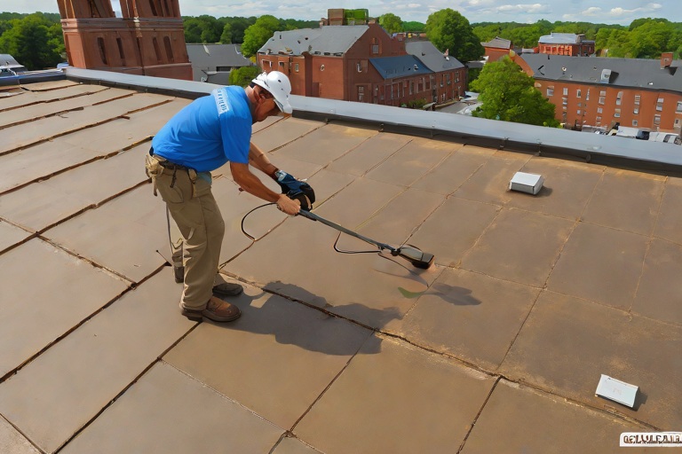
The testing procedure followed a stratified random sampling method across the roof's field and perimeter zones. Using a digital force gauge calibrated to ASTM E488 standards, we applied a perpendicular tensile load to the fastener head. The load was increased incrementally until a definitive failure occurred or the maximum design threshold was reached. This allows us to differentiate between a "pull-out" failure, where the fastener slides out of the steel, and a "pull-through" failure, where the fastener head shears through the roofing membrane or the steel deck itself.

  • Utilization of digital load cells with a precision tolerance of +/- 1%.
  • Strategic sampling focused on high-stress perimeter zones and internal field areas.
  • Application of perpendicular force to eliminate shear bias during the pull sequence.
  • Documentation of peak load values prior to the onset of structural yielding.
  • Comparison of field results against manufacturer-specified minimums for 22-gauge substrates.

Withdrawal Resistance Thresholds and Structural Integrity

The structural integrity of a pharmaceutical facility depends heavily on the gauge of the steel deck. A 22-gauge corrugated deck provides a significantly more robust substrate than the common 24-gauge alternatives, offering a thicker cross-section for the fastener threads to engage. However, the effectiveness of the fastener is governed by the "bite"—the depth of thread engagement within the steel. Our audit focused on establishing the minimum withdrawal resistance thresholds required to maintain the building envelope's continuity under extreme weather events.

When analyzing the results, we looked for a consistent resistance profile. A failure to meet the minimum threshold typically indicates one of three things: improper fastener length, over-driven screws that have stripped the threads, or a mismatch between the fastener diameter and the deck gauge. In a high-stakes pharmaceutical environment, any deviation from the engineering schedule can lead to localized membrane failure, which in turn compromises the clean-room pressures and internal environmental controls of the facility.

  • Minimum withdrawal resistance calculated based on ASCE 7 wind-load requirements.
  • Analysis of thread engagement depth to ensure maximum shear capacity.
  • Evaluation of the "pull-through" resistance of the roofing membrane attachment plates.
  • Assessment of the corrugated profile's influence on fastener perpendicularity.
  • Verification of the load-bearing capacity of the steel deck at the point of attachment.

Fastener Corrosion Diagnostics and Metallurgical Failure

Beyond the mechanical strength of the fastener, the metallurgical condition of the steel-to-fastener interface is critical. Pharmaceutical facilities often utilize aggressive cleaning agents and specialized HVAC systems that can lead to unique atmospheric conditions within the building envelope. We conducted a detailed corrosion diagnostic on the extracted fasteners to identify signs of galvanic corrosion or oxidation. If the fastener coating is compromised, the resulting rust creates a volumetric expansion that can actually loosen the fastener's grip on the 22-gauge steel, effectively reducing the withdrawal resistance over time.

Our analysis focused on the integrity of the zinc-carbon or galvanized coatings. We observed that in areas where the coating had been breached during installation—likely due to over-torquing—pitting corrosion had begun to take hold. This metallurgical degradation is a silent killer of roofing systems; the fastener may appear secure during a visual inspection, but the internal structural bond is compromised. We utilized ASTM B117 standards to evaluate the salt-spray and chemical resistance of the fasteners to ensure they were appropriate for the facility's specific chemical exposure profile.

  • Inspection for "white rust" (zinc oxidation) and "red rust" (base metal oxidation).
  • Evaluation of galvanic incompatibility between the fastener alloy and the steel deck.
  • Assessment of coating thickness and uniformity using magnetic gauge testing.
  • Analysis of the impact of pharmaceutical off-gassing on fastener longevity.
  • Identification of stress-corrosion cracking in high-tension perimeter fasteners.

Wind-Zone Schedules and Envelope Compliance

The final phase of the audit involved reconciling the pull-test data with the facility's wind-zone schedules. Commercial pharmaceutical plants are often large-footprint structures, making them susceptible to significant wind uplift, particularly at the corners and roof edges. The fastening schedule must be designed to transfer these uplift forces from the membrane, through the fastener, and into the structural steel deck. Our findings indicated that while the field fasteners were compliant, the perimeter zones required a higher density of attachments to meet the required safety factors for the designated wind zone.

To bring the facility into full compliance, we recommended a revised fastening pattern that increases the frequency of attachments in the "Zone 2" and "Zone 3" areas of the roof. This ensures that the building envelope remains intact even during a peak wind event, preventing the catastrophic failure of the roofing system and the subsequent contamination of the production floors below. By aligning the mechanical pull-test results with the ASCE 7-16 wind load maps, we provided Aquashield Corporate with a data-driven roadmap for structural remediation and long-term envelope maintenance.

  • Cross-referencing pull-test data with ASCE 7-16 wind-uplift coefficients.
  • Recalculation of fastener spacing for perimeter and corner zones to increase safety margins.
  • Verification of the continuity of the building envelope from the roof deck to the parapet.
  • Implementation of a quarterly monitoring schedule for high-stress attachment points.
  • Final certification of the roofing system's ability to withstand design-basis wind speeds.

Aquashield Roofing Corporation

4006 Morris Ct.
Chesapeake, VA 23323
Direct Line: 757-553-5191
GPS Coordinates: 36.755164, -76.353932

Official Facebook Updates

Virginia Beach Roofing Company - Roofing Service Virginia Beach VA, Roofing Contractor

585 S Birdneck Rd #106
Virginia Beach, VA 23451
Direct Line: +17576318100
Google Maps Plus Code: RXCX+V7 Virginia Beach, Virginia
GPS Coordinates: 36.822156, -76.001565
Commercial Engineering Dossier #686

Electronic Vector Mapping (EVM) Low-Voltage Membrane Breach Detection on Commercial Historic Sanctuary & Education Annexs

Industrial Building Envelope Sciences • Commercial Low-Slope Systems
Electronic Vector Mapping (EVM) Low-Voltage Membrane Breach Detection on Commercial Historic Sanctuary & Education Annexs

The Challenge of Historic Envelope Integrity in Complex Sanctuary Geometries

When managing the building envelope of a historic sanctuary and its accompanying education annexes, the primary engineering challenge is the mitigation of risk associated with complex roof geometries and high-value interior assets. Historic structures often feature intricate flashing details, varying pitch transitions, and aging substrates that make traditional leak detection methods inadequate. In these environments, a failure in the membrane is not merely a maintenance issue; it is a threat to irreplaceable architectural archives and structural timber. The objective of this audit was to establish a zero-tolerance threshold for moisture ingress by implementing a high-precision electronic monitoring system.

Traditional moisture detection relies heavily on visual inspection or infrared thermography, both of which are reactive rather than proactive. Infrared scanning requires a significant thermal differential to identify saturated insulation, meaning by the time a leak is visible on a camera, the building envelope has already been compromised for days or weeks. For the Sanctuary and Education Annex, we required a proactive, non-destructive testing (NDT) protocol that could certify the membrane's integrity before the final capping layers were fully integrated, ensuring that no microscopic punctures existed in the primary waterproofing layer.

  • Mitigation of hydrostatic pressure buildup at valley transitions and parapet walls.
  • Protection of sensitive interior archives from capillary action and vapor drive.
  • Reduction of long-term operational expenditures by eliminating "find-and-fix" leak cycles.
  • Preservation of historic masonry by preventing saturated substrate saturation.

Technical Architecture of Electronic Vector Mapping (EVM)

The core of our engineering approach involved the installation of a conductive underlayment vector grid. Unlike standard membranes, the EVM system utilizes a specialized conductive layer that acts as a continuous electrical circuit. By applying a low-voltage, high-frequency current across the membrane, we create a stable electrical field. Any breach in the membrane—even one invisible to the naked eye—interrupts the current or creates a localized change in resistance. This allows the system to map the roof as a digital coordinate plane, turning the entire roof surface into a giant sensor.

The vectoring process relies on the principle of electrical continuity. The grid is divided into intersecting X and Y axes of conductive strips, separated by a dielectric insulator. When a puncture occurs, the low-voltage current seeks the path of least resistance, leaking through the breach. The EVM hardware detects the exact intersection of the compromised vectors, allowing our team to pinpoint the breach location within a few square inches across thousands of square feet of roofing. This level of precision is unattainable with traditional flood testing, which often damages the substrate or requires excessive water usage that can stress historic drainage systems.

  • Utilization of low-voltage DC current to prevent electrolysis or corrosion of metal flashing.
  • Implementation of a dielectric barrier to prevent false positives from structural steel contact.
  • Integration of a digital signal processor (DSP) to filter out electromagnetic interference (EMI).
  • Calibration of the grid to account for the specific resistivity of the sanctuary's roof slope.

Pinpointing Microscopic Pinhole Punctures and Installation Defects

In commercial roofing, the most dangerous leaks are not the large tears, but the microscopic pinhole punctures. These often occur during the installation process—such as a dropped tool or a fastener that slightly pierces the membrane—or through thermal cycling where the coefficient of expansion differs between the membrane and the substrate. These pinholes allow moisture to enter via vapor drive or wind-driven rain, which then migrates along the underside of the membrane, often surfacing feet away from the actual entry point. This "migration effect" is what makes traditional leak detection a guessing game.

By employing Electronic Vector Mapping, we eliminated the guesswork. During the audit of the Education Annex, the EVM system identified three distinct pinhole breaches that were completely invisible during a standard ASTM-compliant visual inspection. Because the system monitors the electrical integrity of the membrane in real-time, we were able to see the "leak" as a drop in voltage at a specific vector coordinate. This allowed our craftsmen to perform a surgical repair, applying a targeted heat-weld patch to the exact coordinate without having to strip large sections of the roof to find the source.

  • Identification of "invisible" breaches caused by mechanical stress during membrane rollout.
  • Elimination of the "migration gap" between the entry point and the interior leak site.
  • Prevention of moisture accumulation in the insulation layer, avoiding the risk of mold growth.
  • Validation of seam integrity across high-stress transition points and flashing laps.

Non-Destructive Quality Certification and Lifecycle Analysis

The final phase of the project was the issuance of a Non-Destructive Quality Certification. For the owners of the sanctuary, this certification serves as a "birth certificate" for the roof, proving that the envelope was 100% sealed at the time of completion. This is a critical component of building envelope engineering, as it shifts the liability from the owner to the installer and provides a baseline for future maintenance. By using EVM, we provided a quantitative data set—a digital map of the roof's integrity—rather than a qualitative "best effort" report.

From a material science perspective, the integration of a conductive grid provides a permanent diagnostic tool. Should a breach occur ten years from now due to extreme weather or foot traffic, the system can be re-energized to locate the new breach instantly. This transforms the roof from a passive shield into an active building component. This approach aligns with ANSI standards for commercial roofing and exceeds the requirements for historic preservation, ensuring that the sanctuary and its annexes remain dry and structurally sound for the next half-century.

  • Provision of a certified "Zero-Leak" digital map for insurance and warranty documentation.
  • Reduction of future maintenance costs by enabling targeted, surgical repairs.
  • Alignment with ASTM E2128 standards for the evaluation of moisture-tight envelopes.
  • Extension of the overall lifecycle of the roof system through proactive monitoring.

Aquashield Roofing Corporation

4006 Morris Ct.
Chesapeake, VA 23323
Direct Line: 757-553-5191
GPS Coordinates: 36.755164, -76.353932

Official Facebook Updates

Virginia Beach Roofing Company - Roofing Service Virginia Beach VA, Roofing Contractor

585 S Birdneck Rd #106
Virginia Beach, VA 23451
Direct Line: +17576318100
Google Maps Plus Code: RXCX+V7 Virginia Beach, Virginia
GPS Coordinates: 36.822156, -76.001565
Commercial Engineering Dossier #687

Liquid-Applied PMMA & Polyurethane Fleece-Reinforced Flashing Resins on Commercial Financial Institution Data Vaults

Industrial Building Envelope Sciences • Commercial Low-Slope Systems
Liquid-Applied PMMA & Polyurethane Fleece-Reinforced Flashing Resins on Commercial Financial Institution Data Vaults

The Engineering Challenge of Data Vault Building Envelopes

In the realm of commercial building envelope engineering, few environments demand the absolute precision and reliability of a financial institution data vault. These structures are not merely rooms; they are fortified assets where the failure of a single flashing detail can lead to catastrophic data loss or structural compromise. The primary challenge lies in the intersection of heavy structural steel—specifically I-beam stanchions—and the external weather-tight membrane. These stanchions create complex, multi-planar geometries that are notorious for trapping moisture through capillary action and creating stress concentrations during thermal expansion and contraction.

A traditional approach using sheet membranes often fails at these intricate junctions because the material cannot conform perfectly to the tight radii of the I-beam flanges. This results in "fish-mouths" or bridging, where the membrane pulls away from the substrate, creating a direct path for water ingress. To mitigate these risks, our engineering audit focuses on a liquid-applied system that eliminates seams and provides a monolithic bond to the substrate, ensuring that the envelope behaves as a single, continuous barrier.

  • Elimination of mechanical fasteners that create puncture points in the waterproofing layer.
  • Mitigation of hydrostatic pressure buildup at the base of structural stanchions.
  • Reduction of thermal bridging that can lead to interstitial condensation within the vault walls.
  • Enhanced resistance to the high-vibration environments typical of heavy-duty HVAC systems supporting data centers.

Material Science of PMMA and Polyurethane Resins

The selection of Polymethyl Methacrylate (PMMA) cold-applied resins represents a significant leap in material science for commercial roofing. Unlike traditional hot-applied rubbers or bitumen, PMMA is a thermosetting plastic that undergoes a rapid polymerization process. This chemical reaction occurs regardless of temperature or humidity, making it an ideal choice for the strict timelines of financial institution maintenance. The resin provides an exceptionally high bond strength to a variety of substrates, including galvanized steel, concrete, and existing polymer membranes, ensuring that the flashing does not delaminate under extreme weather cycles.

Complementing the PMMA is the use of high-performance polyurethane resins for specific priming and sealing phases. The synergy between these two chemistries allows for a graded transition of elasticity. While the PMMA provides the hard, durable, and UV-stable outer shell, the polyurethane components offer the necessary flexibility to accommodate the minute structural shifts of the building's skeleton. This dual-resin approach ensures that the flashing system can withstand the rigorous demands of ASTM standards for water penetration and air leakage.

  • Rapid polymerization kinetics allowing for foot traffic and full cure within hours rather than days.
  • Superior UV stability preventing the degradation and embrittlement common in standard PVC or TPO membranes.
  • Low viscosity during application, allowing the resin to penetrate the microscopic pores of the substrate for a mechanical lock.
  • Chemical resistance to industrial pollutants and atmospheric contaminants common in urban financial districts.

Mechanics of Fleece-Reinforcement Embedding

To transform a liquid resin from a simple coating into a structural flashing system, we employ a specialized fleece-reinforcement embedding process. This is not a mere layering technique but the creation of a fiber-reinforced polymer (FRP) composite. The process involves a "sandwich" application: a base coat of PMMA resin is applied, followed by the immediate embedding of a non-woven polyester fleece, which is then saturated with a second layer of resin. This embedding process ensures that the fleece is fully encapsulated, preventing any air voids or moisture pockets from forming within the membrane.

The primary engineering benefit of the fleece is the distribution of tensile stress. When the I-beam stanchions expand or contract due to temperature fluctuations, the fleece acts as a structural bridge, absorbing the movement and preventing the resin from cracking. This is particularly critical at the "crotch" of the I-beam, where the change in direction is most abrupt. By reinforcing these high-stress zones, we create a flashing detail that is virtually immune to the fatigue cracking that plagues traditional flashing methods.

  • Increased puncture resistance and tear strength through the integration of high-tenacity polyester fibers.
  • Ability to bridge existing cracks or gaps in the substrate without the risk of reflective cracking.
  • Enhanced dimensional stability, ensuring the membrane maintains its thickness across complex geometries.
  • Creation of a seamless, monolithic transition from the horizontal roof deck to the vertical stanchion faces.

Execution, Cure Kinetics, and Quality Assurance

The execution of a PMMA and polyurethane system requires a master tradesman's precision, as the rapid cure kinetics leave no room for error. The application window is tight; once the catalyst is mixed with the resin, the polymerization begins immediately. Our technicians utilize a precise "wet-on-wet" technique, ensuring the fleece is embedded while the base resin is still in its liquid phase. This ensures a chemical bond between layers, rather than a mechanical bond, which significantly increases the long-term durability of the envelope.

Quality assurance is conducted through a rigorous engineering audit that mirrors ANSI standards for commercial waterproofing. Following the cure, the flashing is subjected to a series of non-destructive tests to verify the integrity of the seal. We utilize infrared thermography to detect any subsurface voids or moisture entrapment and perform electronic leak detection (ELD) to ensure the continuity of the membrane. This level of scrutiny is mandatory for data vaults, where the cost of a leak far outweighs the cost of the most premium material application.

  • Strict adherence to substrate preparation, including diamond grinding and solvent cleaning to ensure a surface profile (CSP) conducive to bonding.
  • Utilization of precision mixing equipment to maintain the exact stoichiometric ratio of resin to catalyst.
  • Implementation of flood testing on critical flashing junctions to simulate extreme precipitation events.
  • Final verification via a comprehensive building envelope audit, documenting every transition point and seal.

Aquashield Roofing Corporation

4006 Morris Ct.
Chesapeake, VA 23323
Direct Line: 757-553-5191
GPS Coordinates: 36.755164, -76.353932

Official Facebook Updates

Virginia Beach Roofing Company - Roofing Service Virginia Beach VA, Roofing Contractor

585 S Birdneck Rd #106
Virginia Beach, VA 23451
Direct Line: +17576318100
Google Maps Plus Code: RXCX+V7 Virginia Beach, Virginia
GPS Coordinates: 36.822156, -76.001565
Commercial Engineering Dossier #688

Commercial Expansion Joint Bellows & Heavy-Gauge Neoprene Movement Transitions on Commercial Telecommunications Central Switching Offices

Industrial Building Envelope Sciences • Commercial Low-Slope Systems
Commercial Expansion Joint Bellows & Heavy-Gauge Neoprene Movement Transitions on Commercial Telecommunications Central Switching Offices

Structural Dynamics and Load Distribution in Central Switching Offices

Telecommunications Central Switching Offices (CSOs) represent a unique challenge in commercial building envelope engineering due to their extreme internal load variances. Unlike standard warehouse or office structures, CSOs house massive battery arrays, high-capacity power plants, and dense switching gear that create significant concentrated dead loads. These loads often result in uneven structural compression across the building's footprint, necessitating a sophisticated approach to structural articulation. When these facilities are constructed as multi-wing complexes, the interaction between different structural masses leads to complex movement patterns that can compromise a standard roofing system.

The primary engineering concern in these environments is the management of thermal expansion and contraction combined with the vibration induced by heavy HVAC and power equipment. If the building envelope is too rigid, the resulting stress manifests as shear cracks in the parapets or catastrophic failure of the roof membrane at the transition points. To mitigate this, we implement strategic expansion joints that allow the building to "breathe" without sacrificing the integrity of the weather barrier.

  • Concentrated Dead Loads: Heavy machinery creates localized settlement patterns that differ from the perimeter shell.
  • Thermal Cycling: Large roof surface areas experience significant expansion and contraction, putting stress on the perimeter tie-ins.
  • Vibrational Fatigue: Constant oscillation from industrial cooling systems can lead to the degradation of rigid sealants.
  • Structural Articulation: The necessity of dividing the building into independent structural blocks to prevent uncontrolled cracking.

Engineering Analysis of Differential Settlement and Multi-Wing Movement

Differential settlement occurs when the soil beneath one portion of the CSO settles more than another, often caused by the aforementioned concentrated equipment loads. In a multi-wing configuration, this creates a "differential displacement" where two connected sections of the building move independently in three-dimensional space. From a roofing perspective, this movement is not merely horizontal; it involves torsional twisting and vertical shifting. If the roofing membrane is not engineered to accommodate this specific displacement, the material will reach its ultimate elongation point and rupture.

Our audit focuses on the "critical movement zone," which is the interface where two structural wings meet. In these zones, we move away from standard modified bitumen or TPO membranes and instead utilize heavy-gauge neoprene movement transitions. These transitions act as a structural fuse, absorbing the energy of the building's movement and preventing that stress from transferring to the primary field membrane. The engineering goal is to ensure that the movement is absorbed by the expansion joint rather than the flashing or the substrate.

  • Torsional Stress: The twisting motion caused by uneven settlement that can tear traditional flashing.
  • Ultimate Elongation: The maximum distance a material can stretch before failure, a critical metric for neoprene selection.
  • Shear Force Management: Utilizing sliding plates and elastomeric bellows to redirect lateral forces.
  • Substrate Compatibility: Ensuring the transition membrane is chemically compatible with the primary roof system to prevent delamination.

Material Science of Heavy-Gauge Neoprene and Elastomeric Bellows

For high-movement areas in CSOs, we specify heavy-gauge neoprene and elastomeric bellows because of their superior resilience and resistance to ozone and UV degradation. Neoprene, a polychloroprene polymer, offers a unique combination of mechanical strength and flexibility. Unlike standard rubberized membranes, heavy-gauge neoprene maintains its elasticity across a wide temperature range, which is essential for facilities that maintain strict internal climate controls while facing extreme external weather fluctuations. We adhere to ASTM D2000 standards to ensure the material's hardness and tensile strength meet the rigorous demands of a commercial switching office.

The "bellows" design is a critical engineering feature. By folding the elastomeric material into a series of convolutions, we increase the effective length of the material without increasing the footprint of the joint. This allows the joint to expand and contract like an accordion, accommodating significant axial and lateral movement. This geometry ensures that the material is not stretched to its limit but rather unfolds, significantly extending the fatigue life of the joint and reducing the frequency of required maintenance cycles.

  • ASTM D2000 Compliance: Ensuring the neoprene meets specific industrial standards for durability and chemical resistance.
  • Hysteresis Loss: Minimizing the energy loss during expansion and contraction to prevent permanent deformation of the bellows.
  • UV Stabilization: Utilizing carbon-black additives in the neoprene to prevent premature cracking from solar radiation.
  • Multi-Axial Flexibility: The ability of the bellows to handle movement in multiple planes simultaneously.

Execution of Watertight Tie-ins and Envelope Auditing

The most common point of failure in commercial expansion joints is not the joint itself, but the tie-in where the movement transition meets the primary roof membrane. A master-level installation requires a redundant layering strategy. We begin with a mechanical fastening system to secure the neoprene bellows to the structural steel, followed by a high-performance flashing transition. We utilize a combination of heat-welded membranes and liquid-applied elastomeric sealants to create a seamless, monolithic barrier. This "belt and suspenders" approach ensures that even if one layer is compromised, the secondary barrier prevents water infiltration into the sensitive electronic equipment below.

The final stage of the engineering process is the rigorous audit and testing phase. We employ infrared thermography to detect hidden moisture pockets and perform flood testing on the transition zones to verify watertightness. Because CSOs are mission-critical facilities, the tolerance for leaks is zero. Our maintenance protocol involves quarterly inspections of the bellows' compression sets to ensure the material has not "bottomed out" or lost its recovery capacity. By treating the expansion joint as a living part of the building's anatomy, we ensure the long-term viability of the building envelope.

  • Redundant Flashing: Layering liquid-applied membranes over heat-welded seams for maximum security.
  • Mechanical Anchoring: Using stainless steel clamping bars to prevent the bellows from pulling away during maximum expansion.
  • Infrared Thermography: Utilizing thermal imaging to identify anomalies in the envelope's thermal bridge.
  • Compression Set Analysis: Monitoring the ability of the neoprene to return to its original shape after a movement event.

Aquashield Roofing Corporation

4006 Morris Ct.
Chesapeake, VA 23323
Direct Line: 757-553-5191
GPS Coordinates: 36.755164, -76.353932

Official Facebook Updates

Virginia Beach Roofing Company - Roofing Service Virginia Beach VA, Roofing Contractor

585 S Birdneck Rd #106
Virginia Beach, VA 23451
Direct Line: +17576318100
Google Maps Plus Code: RXCX+V7 Virginia Beach, Virginia
GPS Coordinates: 36.822156, -76.001565
Commercial Engineering Dossier #689

Commercial Kitchen Grease Containment & 304 Stainless Steel Catchment Shielding on Commercial Heavy Manufacturing Fabrication Plants

Industrial Building Envelope Sciences • Commercial Low-Slope Systems
Commercial Kitchen Grease Containment & 304 Stainless Steel Catchment Shielding on Commercial Heavy Manufacturing Fabrication Plants

The Chemistry of Lipid Degradation on Polymer Membranes

In the context of heavy manufacturing fabrication plants that incorporate industrial-scale kitchens or food processing units, the building envelope faces a unique and aggressive chemical threat: animal fat lipids. As a master roofer, I have observed that most facility managers underestimate the volatility of airborne grease and liquid lipid runoff. When these fats escape the ventilation system or leak from rooftop grease traps, they do not simply sit on the surface of the roofing membrane; they initiate a complex chemical reaction known as plasticizer migration.

Single-ply membranes, particularly PVC (Polyvinyl Chloride) and TPO (Thermoplastic Polyolefin), rely on specific chemical additives to maintain flexibility and elongation. Animal fats act as potent solvents that penetrate the polymer matrix, leaching out these essential plasticizers. This process leads to "embrittlement," where the membrane loses its elasticity, becomes prone to hairline fractures, and eventually suffers from catastrophic splitting under thermal expansion and contraction cycles.

  • Plasticizer Migration: The process where lipids force the leaching of stabilizing chemicals from the membrane, causing the material to shrink and harden.
  • Chemical Softening: In some instances, the membrane may initially appear to soften or "gum up," creating a tacky surface that attracts more debris and pollutants.
  • Thermal Acceleration: High exhaust temperatures from kitchen vents accelerate the chemical breakdown of the membrane, creating a localized "hot zone" of degradation.
  • Puncture Vulnerability: Once the lipid degradation begins, the membrane's tensile strength drops, making it susceptible to punctures from standard maintenance foot traffic.

Engineering the 304 Stainless Steel Catchment Shielding

To mitigate the risk of lipid-induced failure, we implement a rigorous shielding strategy utilizing 304-grade stainless steel. Standard galvanized steel or aluminum is insufficient in these environments due to the acidic nature of decomposed fats and the caustic cleaning agents used in industrial kitchens. 304 Stainless Steel is selected for its superior chromium-nickel composition, which provides an inert surface that resists pitting and corrosion even when exposed to high-temperature grease runoff.

The engineering of the catchment box is critical. We do not simply place a pan on the roof; we design a fully integrated shielding system that isolates the grease source from the building envelope. The system features a custom-fabricated 304 SS tray with a precision-engineered slope toward a dedicated collection point. This ensures that lipids are channeled away from the roof seams and flashing, which are the most vulnerable points of any commercial roofing system.

  • TIG Welding: All joints in the catchment shielding are TIG (Tungsten Inert Gas) welded to ensure a hermetic seal, preventing any lipid seepage into the substrate.
  • Thermal Expansion Gaps: The shielding is installed with calculated expansion joints to prevent the steel from buckling or shearing the membrane during extreme temperature swings.
  • Positive Drainage: A minimum 1/4" per foot slope is maintained within the catchment box to prevent stagnant grease ponds.
  • Mechanical Fastening: The system is secured using non-penetrating weighted bases or specialized oversized flashing boots to maintain the integrity of the waterproofing layer.

Sacrificial Chemical-Resistant Coatings and Barrier Layers

While stainless steel provides the primary defense, the surrounding "splash zone" requires a secondary layer of protection. We utilize sacrificial chemical-resistant coatings—typically high-build polyureas or modified epoxy resins—to create a sacrificial barrier over the primary single-ply membrane. The philosophy here is simple: it is far more cost-effective to recoat a sacrificial layer every three to five years than to replace a full roof section due to lipid degradation.

These coatings are engineered to have a high cross-link density, which prevents small-molecule lipids from migrating through the coating and reaching the TPO or PVC beneath. By applying this layer in a thick, monolithic sheet, we eliminate the seams that grease typically exploits. The coating acts as a "sacrificial anode" in a chemical sense, absorbing the brunt of the lipid attack and protecting the structural integrity of the building envelope.

  • High-Build Polyurea: A rapid-cure coating that provides an impermeable shield against animal fats and caustic cleaning chemicals.
  • Elastomeric Properties: The coating must maintain a degree of flexibility to move with the roof's natural thermal expansion without cracking.
  • Surface Profiling: Before application, the membrane is mechanically scrubbed and chemically degreased to ensure a molecular bond between the coating and the polymer.
  • Maintenance Cycle: The sacrificial layer is audited quarterly; once "pitting" or discoloration occurs, the layer is stripped and reapplied.

Audit Methodology and Long-Term Envelope Integrity

A professional engineering audit of a heavy manufacturing plant's roof requires more than a visual walk-through. We employ a multi-phase diagnostic approach to ensure the building envelope remains airtight and watertight. The primary focus is the interface between the 304 stainless steel shielding and the membrane. This is where most failures occur, as the difference in thermal expansion coefficients between steel and polymer can create gaps that allow grease to seep into the insulation board.

We adhere to ASTM and ANSI standards for testing, utilizing infrared thermography to detect subsurface moisture or grease pockets that are not visible to the naked eye. By analyzing the thermal signature of the roof, we can identify "hot spots" where grease has saturated the insulation, potentially compromising the R-value and creating a breeding ground for microbial growth. This data-driven approach allows us to move from reactive repairs to a predictive maintenance model.

  • Infrared Thermography: Used to detect hidden lipid saturation and moisture entrapment within the roof assembly.
  • ASTM E2127 Compliance: Implementing standard practices for detecting leaks in synthetic roofing membranes.
  • Seam Integrity Testing: Utilizing vacuum testing on all heat-welded seams surrounding the grease containment zones.
  • Envelope Lifecycle Analysis: Calculating the degradation rate of the sacrificial coatings to schedule reapplications before the primary membrane is exposed.

Aquashield Roofing Corporation

4006 Morris Ct.
Chesapeake, VA 23323
Direct Line: 757-553-5191
GPS Coordinates: 36.755164, -76.353932

Official Facebook Updates

Virginia Beach Roofing Company - Roofing Service Virginia Beach VA, Roofing Contractor

585 S Birdneck Rd #106
Virginia Beach, VA 23451
Direct Line: +17576318100
Google Maps Plus Code: RXCX+V7 Virginia Beach, Virginia
GPS Coordinates: 36.822156, -76.001565
Commercial Engineering Dossier #690

Masonry Parapet Counterflashing Reglet Overhauls & Polyurethane Sealant Compression on Commercial Logistics Distribution Hubs

Industrial Building Envelope Sciences • Commercial Low-Slope Systems
Masonry Parapet Counterflashing Reglet Overhauls & Polyurethane Sealant Compression on Commercial Logistics Distribution Hubs

The Mechanics of Parapet Failure in High-Volume Logistics Hubs

In the realm of commercial building envelope engineering, logistics distribution hubs present a unique set of challenges due to their massive footprints and extreme thermal exposure. The parapet wall, acting as the critical transition between the horizontal roofing membrane and the vertical masonry facade, is the primary point of failure for water infiltration. In these facilities, the primary catalyst for failure is typically the degradation of the counterflashing reglet—the recessed slot where the metal flashing is embedded into the masonry.

Over time, the coefficient of thermal expansion causes the masonry and the metal flashing to move at different rates. When the original installation relies on thin-gauge metal or substandard sealants, the bond fails, creating a capillary pathway for wind-driven rain to penetrate the building envelope. Once water enters the reglet, it bypasses the primary roofing membrane and migrates directly into the wall cavity, leading to interior mold, structural efflorescence, and the compromise of warehouse inventory.

  • Thermal cycling causing cyclical expansion and contraction of the masonry substrate.
  • Failure of legacy sealants due to UV degradation and loss of elasticity.
  • Capillary action drawing moisture deep into the masonry core behind the flashing.
  • Insufficient gauge thickness in original flashing leading to "oil-canning" and joint separation.

Precision Reglet Engineering and Mortar Joint Grinding

To rectify these systemic failures, a comprehensive overhaul of the reglet system is required. This is not a superficial patching job but a surgical engineering process. The first step involves the strategic grinding of mortar joints to create a clean, consistent receiving slot for the new counterflashing. Using industrial-grade diamond grinding wheels, we remove the compromised mortar and old sealant to a depth of 3/4 of an inch, ensuring the reglet is perfectly level and free of debris.

This process of grinding is critical because it allows the flashing to sit flush against the masonry, eliminating the gaps that typically allow water to seep behind the metal. By creating a precise, uniform channel, we ensure that the flashing is mechanically supported by the masonry rather than relying solely on the adhesive strength of the sealant. This approach adheres to the highest standards of commercial craftsmanship, ensuring that the flashing remains stable even under high wind-load pressures common in open-lot distribution centers.

  • Utilization of variable-speed grinders with vacuum shrouds to maintain a dust-free environment.
  • Precision depth gauging to ensure a consistent 3/4" reglet depth across the entire perimeter.
  • Mechanical cleaning of the masonry substrate to remove all efflorescence and loose particulates.
  • Verification of the reglet alignment to prevent "bowing" of the metal flashing during installation.

Material Science: Heavy-Gauge Kynar and Polyurethane Compression

The selection of materials is where engineering meets longevity. For logistics hubs, we specify heavy-gauge Kynar 500/700 coated steel. Unlike standard galvanized steel, Kynar provides a superior fluoropolymer finish that resists chalking and fading under intense UV exposure. We employ a heavier gauge—typically 22 or 24 gauge—to provide the structural rigidity necessary to resist deformation. This thickness ensures that the flashing maintains its shape and seal despite the immense thermal shifts experienced by large-scale industrial warehouses.

However, the metal is only as effective as the sealant that bonds it to the masonry. We utilize high-performance polyurethane sealants, specifically those meeting ASTM C920 standards for elastomeric joint sealants. The key to a permanent seal is "compression." Rather than simply filling the gap, we engineer the joint to allow the polyurethane to compress and expand. By applying the sealant in a controlled "hourglass" geometry within the reglet, we ensure that the sealant can stretch without tearing away from the substrate, effectively creating a waterproof gasket between the Kynar flashing and the masonry.

  • Kynar 500 coating for maximum UV resistance and chemical stability.
  • Heavy-gauge steel to eliminate thermal warping and structural vibration.
  • ASTM C920 compliant polyurethane sealants for superior adhesion to porous masonry.
  • Implementation of a two-stage sealant application: a backing rod for depth control and a polyurethane cap for the weather seal.

Systemic Integration and Long-Term Envelope Integrity

The final phase of the overhaul is the systemic integration of the counterflashing with the primary roofing membrane. The counterflashing must overlap the base flashing by a minimum of four inches to ensure a positive drainage plane. This ensures that any water that manages to penetrate the primary sealant line is directed away from the wall and onto the roof membrane, where it can be efficiently managed by the facility's drainage system. This "redundant" layering is the hallmark of a professional building envelope audit.

Once the installation is complete, the integrity of the seal is verified through rigorous inspection. The result is a monolithic barrier that stops wall leaks at the source. By combining precision masonry grinding, high-spec material science, and the physics of sealant compression, we transform a vulnerable point of entry into a fortified component of the building envelope. This comprehensive approach not only protects the structural integrity of the logistics hub but also reduces long-term maintenance costs and prevents costly operational downtime caused by interior leaks.

  • Verification of the 4-inch minimum overlap to ensure a positive slope for water shedding.
  • Post-installation flood testing of critical joints to confirm zero infiltration.
  • Documentation of all material batches and installation dates for facility maintenance records.
  • Final audit of the building envelope to ensure seamless transition from roof to wall.

Aquashield Roofing Corporation

4006 Morris Ct.
Chesapeake, VA 23323
Direct Line: 757-553-5191
GPS Coordinates: 36.755164, -76.353932

Official Facebook Updates

Virginia Beach Roofing Company - Roofing Service Virginia Beach VA, Roofing Contractor

585 S Birdneck Rd #106
Virginia Beach, VA 23451
Direct Line: +17576318100
Google Maps Plus Code: RXCX+V7 Virginia Beach, Virginia
GPS Coordinates: 36.822156, -76.001565
Commercial Engineering Dossier #691

Flute-Fill EPS/Polyiso Insulation Sizing for Standing Rib Metal Roof Retrofits on Commercial Automotive Assembly Plants

Industrial Building Envelope Sciences • Commercial Low-Slope Systems
Flute-Fill EPS/Polyiso Insulation Sizing for Standing Rib Metal Roof Retrofits on Commercial Automotive Assembly Plants

The Engineering Challenge of Corrugated Substrates in Automotive Facilities

During a comprehensive building envelope audit of a large-scale automotive assembly plant, the primary vulnerability identified was the existing standing rib metal roof system. In these industrial environments, the roof is subjected to extreme thermal cycling and high internal humidity from painting and curing processes. The fundamental engineering flaw in traditional retrofit attempts on these structures is the tendency to overlay insulation directly atop the rib peaks, leaving the "valleys" or flutes of the metal decking empty. This creates massive void spaces that compromise the entire thermal assembly.

From a master roofer's perspective, these voids are not merely empty spaces; they are conduits for convective heat loss. When insulation is only placed on the peaks, the corrugated metal acts as a thermal bridge, rapidly conducting heat away from the conditioned interior. Furthermore, these gaps allow for the accumulation of condensation, which can lead to premature corrosion of the structural steel decking. To achieve a truly high-performance envelope, the engineering objective must shift from simple coverage to complete volumetric filling of the roof profile.

  • Identification of "thermal bypass" zones where conditioned air escapes through rib voids.
  • Analysis of structural deflection in long-span automotive bays affecting roof drainage.
  • Evaluation of existing fastener integrity to ensure the substrate can support additional dead loads.
  • Assessment of the coefficient of thermal expansion between the metal deck and the proposed insulation layers.

Precision-Cut Flute-Fill Geometry and Material Selection

The solution to eliminating void spaces is the implementation of precision-cut flute-fill insulation. This process involves using CNC-milled Expanded Polystyrene (EPS) or Polyisocyanurate (Polyiso) profiles that are engineered to the exact dimensions of the standing rib geometry. By utilizing a "flute-fill" approach, we transform a corrugated surface into a flat, monolithic thermal plane. This is critical for automotive plants where the roof may span hundreds of thousands of square feet, meaning even a minor sizing error can lead to significant gaps across the entire footprint.

Material selection is a balance of R-value and dimensional stability. Polyiso is preferred for its superior thermal resistance per inch, which is essential for meeting stringent energy codes. However, in specific high-compression zones, high-density EPS is utilized for its structural rigidity and ability to maintain the flute shape without compressing over time. The precision of the cut is paramount; a tolerance of more than 1/8th of an inch can create a "chimney effect," where air begins to circulate within the insulation layer, effectively neutralizing the R-value of the assembly.

  • Utilization of CNC-milled templates to ensure a friction-fit within the metal flutes.
  • Application of high-density Polyiso for maximum thermal efficiency in thin profiles.
  • Integration of EPS transition strips to manage irregular roof perimeters and HVAC curbs.
  • Implementation of a staggered joint pattern to prevent linear air leakage through the insulation seams.

Mitigating Thermal Bridging and Air Infiltration

Thermal bridging occurs when a highly conductive material—in this case, the steel roof deck—creates a path of least resistance for heat to travel. In a standard retrofit, the metal ribs act as "thermal highways," bypassing the insulation. By filling these flutes, we effectively break the thermal bridge. The engineering goal is to create a continuous thermal break that separates the interior environment from the exterior elements, adhering to ASTM C663 standards for thermal transmittance.

Beyond heat transfer, air infiltration is a critical concern in automotive assembly plants, where dust control and temperature stability are mandatory for paint shop quality. A flute-fill system, when properly sealed at the perimeters, eliminates the interstitial air spaces where moisture can condense and air can leak. This creates a "tight" envelope that reduces the load on HVAC systems and prevents the infiltration of unfiltered exterior air, which can introduce contaminants into the assembly line.

  • Reduction of the "stack effect" by sealing the vertical gaps within the standing rib profiles.
  • Calculation of the effective R-value by accounting for the reduction in thermal bridging.
  • Application of closed-cell sealants at the intersection of flute-fills and parapet walls.
  • Monitoring of dew point temperatures to ensure condensation does not form within the insulation voids.

Membrane Integration and Long-Term Envelope Stability

Once the flute-fill insulation has established a flat, level substrate, the final phase is the installation of a high-performance single-ply membrane, such as TPO (Thermoplastic Olefin) or PVC. The transition from a corrugated profile to a flat surface is the most critical step for the longevity of the roof. Because the flute-fills have eliminated the "peaks and valleys," the membrane can be installed without the risk of "bridging"—a common failure where the membrane stretches over a rib and eventually tears due to thermal expansion and contraction.

For automotive plants, a fully adhered membrane system is recommended over mechanically attached systems to avoid puncturing the thermal break. The membrane is heat-welded at the seams, creating a waterproof skin that is chemically bonded to the flat insulation surface. This ensures that hydrostatic pressure from ponding water does not force moisture into the insulation layers. The result is a building envelope that is not only thermally efficient but also structurally sound and resistant to the rigors of industrial operation.

  • Installation of a reinforced separation sheet to protect the Polyiso from membrane adhesives.
  • Heat-welding of TPO seams using automated robotic welders for consistent bond strength.
  • Detailing of roof penetrations and HVAC curbs to ensure a watertight seal over the flat substrate.
  • Final flood testing to verify the integrity of the envelope and the efficacy of the drainage slopes.

Aquashield Roofing Corporation

4006 Morris Ct.
Chesapeake, VA 23323
Direct Line: 757-553-5191
GPS Coordinates: 36.755164, -76.353932

Official Facebook Updates

Virginia Beach Roofing Company - Roofing Service Virginia Beach VA, Roofing Contractor

585 S Birdneck Rd #106
Virginia Beach, VA 23451
Direct Line: +17576318100
Google Maps Plus Code: RXCX+V7 Virginia Beach, Virginia
GPS Coordinates: 36.822156, -76.001565

Commercial Engineering Dossier #692

Structural Plywood Deck Re-Nailing Schedules on Commercial Mission-Critical Data Centers

Industrial Building Envelope Sciences • Commercial Low-Slope Systems
Structural Plywood Deck Re-Nailing Schedules on Commercial Mission-Critical Data Centers

The Criticality of the Building Envelope in Mission-Critical Data Centers

In the realm of mission-critical infrastructure, the building envelope is not merely a shell but the primary line of defense for millions of dollars in server hardware and sensitive electronic arrays. For data centers located in coastal regions, the roof system is subject to extreme atmospheric pressures and high-wind uplift events. When we conduct an engineering audit on these structures, we focus heavily on the structural plywood deck, which serves as the critical diaphragm transferring lateral loads to the primary framing. If the decking is improperly fastened, the entire assembly is prone to catastrophic failure during a wind event, leading to roof membrane rupture and subsequent water intrusion.

The physics of wind uplift create a vacuum effect on the leeward side of the building, effectively trying to pull the roof assembly upward and away from the structure. In a mission-critical environment, the tolerance for failure is zero. We evaluate the decking not just as a surface for the membrane, but as a structural component that must meet or exceed ASCE 7 standards for wind loads. The integrity of the plywood deck relies entirely on the fastening schedule, ensuring that the shear forces are distributed evenly across the joists and rafters.

  • Verification of diaphragm continuity to prevent localized deck failure.
  • Analysis of wind-tunnel testing data to determine peak uplift pressures at roof corners and perimeters.
  • Assessment of the moisture content of the plywood to ensure optimal fastener grip.
  • Evaluation of the interaction between the roof membrane's attachment method and the underlying deck fasteners.

Engineering the Fastening Schedule for Coastal High-Wind Zones

A standard nailing pattern is insufficient for the rigors of a coastal data center. As a master roofer, I insist on a rigorous re-nailing schedule that optimizes the "stitch" of the plywood to the framing. The transition from smooth-shank to ring-shank fasteners is the most significant upgrade in a high-wind engineering audit. Ring-shank nails utilize a series of ribs or rings along the shaft that act as mechanical anchors, locking the fastener into the wood fibers. This drastically reduces the likelihood of "nail pop" or gradual withdrawal under the cyclic loading caused by wind gusts.

The deployment of pneumatic nailers allows for the consistency and speed required for large-scale commercial projects, but it requires strict oversight. The pneumatic pressure must be calibrated to ensure the nail head is driven flush with the deck without over-driving, which can crush the wood fibers and compromise the structural integrity of the plywood. Our specified schedules typically demand increased fastener density at the perimeter and corners, where the turbulence and uplift pressures are most severe.

  • Implementation of a 6-inch on-center spacing for field fasteners and 3-inch on-center for perimeter edges.
  • Utilization of 10d or 12d ring-shank nails to ensure deep penetration into the structural members.
  • Strict adherence to nail penetration depths to avoid splitting the grain of the supporting joists.
  • Verification of fastener material, ensuring hot-dipped galvanized coatings to prevent corrosion in salty coastal air.

Material Science and Shear Withdrawal Resistance

The engineering core of a re-nailing project is the verification of shear withdrawal resistance. Withdrawal resistance is the force required to pull a fastener straight out of the substrate, whereas shear resistance is the capacity of the fastener to resist forces acting perpendicular to its axis. In a data center roof, the fasteners must withstand both. The ring-shank design transforms the withdrawal mechanism from a simple friction-based hold to a mechanical interlocking system. This is critical because plywood, as a cross-laminated product, can exhibit different expansion and contraction rates than the solid lumber framing.

From a material science perspective, the interaction between the steel of the nail and the cellulose structure of the plywood is paramount. When a ring-shank nail is driven, it displaces the wood fibers around the rings, creating a permanent deformation that resists movement. We analyze the "withdrawal capacity" based on the species of the wood and the diameter of the fastener. In high-wind zones, the goal is to ensure that the fastener fails before the wood does, or better yet, that the combined system exceeds the maximum calculated uplift force by a safety factor of at least 1.5.

  • Calculation of the "effective grip length" to ensure the nail is sufficiently embedded in the framing.
  • Analysis of the shear plane to prevent the fastener from slicing through the plywood during a lateral load event.
  • Comparison of ring-shank performance versus smooth-shank nails in simulated wind-tunnel pull tests.
  • Evaluation of the impact of plywood grade (e.g., CDX) on the overall holding power of the fasteners.

Audit Methodology and Quality Assurance Protocols

A comprehensive building envelope audit for a data center requires more than a visual inspection; it requires a forensic approach to craftsmanship. We begin by mapping the existing fastening pattern and comparing it against the approved engineering blueprints. Any deviation in the nailing schedule is flagged as a structural deficiency. We employ non-destructive testing, such as high-resolution borescope inspections and thermal imaging, to ensure that the fasteners have penetrated the framing and are not merely "floating" in the decking.

The final stage of the audit is the verification of the "as-built" condition. This involves random sampling of the deck to perform manual pull tests, ensuring that the pneumatic driving was consistent across the entire roof surface. As a specialist, I look for the hallmarks of a master tradesman: clean nail heads, no split grain, and a rhythmic, precise spacing that indicates a disciplined crew. By documenting these findings in a detailed engineering report, Aquashield Corporate provides the client with a certified guarantee that their mission-critical facility is armored against the elements.

  • Execution of a grid-based sampling plan to verify fastener spacing across 10% of the total roof area.
  • Documentation of all "over-driven" or "shiner" nails that require immediate remediation.
  • Verification that all pneumatic equipment was calibrated to the specific wood density of the site.
  • Final certification of the building envelope's compliance with local building codes and ANSI standards.

Aquashield Roofing Corporation

4006 Morris Ct.
Chesapeake, VA 23323
Direct Line: 757-553-5191
GPS Coordinates: 36.755164, -76.353932

Official Facebook Updates

Virginia Beach Roofing Company - Roofing Service Virginia Beach VA, Roofing Contractor

585 S Birdneck Rd #106
Virginia Beach, VA 23451
Direct Line: +17576318100
Google Maps Plus Code: RXCX+V7 Virginia Beach, Virginia
GPS Coordinates: 36.822156, -76.001565
Commercial Engineering Dossier #693

Life-Cycle Cost Analysis (LCCA) on Commercial Cold Storage Freezer Warehouses

Industrial Building Envelope Sciences • Commercial Low-Slope Systems
Life-Cycle Cost Analysis (LCCA) on Commercial Cold Storage Freezer Warehouses

The Engineering Physics of Cold Storage Envelopes

In the realm of commercial building envelope engineering, cold storage freezer warehouses represent the most grueling environment for roofing membranes and insulation systems. Unlike standard ambient warehouses, these facilities operate as massive thermal batteries, creating a permanent and aggressive temperature differential between the interior freezer space and the exterior environment. This delta drives a constant migration of moisture, known as vapor drive, where humid exterior air seeks to penetrate the envelope and condense within the insulation layers. If the vapor barrier is compromised, the result is interstitial condensation, which leads to the degradation of R-value and the eventual failure of the roof deck through corrosion.

From a master roofer's perspective, the engineering audit must begin with a rigorous assessment of the thermal bridging points. Any breach in the continuity of the insulation—specifically at the parapet walls, curb flashings, and penetration points—creates a localized cold spot. These spots are catalysts for ice damming and condensation, which can compromise the structural integrity of the building envelope. To mitigate these risks, we adhere strictly to ASTM standards for vapor retarders and thermal insulation, ensuring that the system is airtight and thermally broken.

  • Analysis of vapor drive and moisture migration patterns across the roof assembly.
  • Evaluation of thermal bridging at perimeter walls and mechanical penetrations.
  • Assessment of membrane tensile strength and elasticity under extreme temperature fluctuations.
  • Verification of ASTM E2280 compliance for vapor retarder performance.
  • Inspection of flashing integrity to prevent capillary action and water infiltration.

Net Present Value and Life-Cycle Cost Analysis

When presenting a Life-Cycle Cost Analysis (LCCA) to a corporate stakeholder, the conversation must shift from immediate Capital Expenditure (CapEx) to Net Present Value (NPV). A common mistake in facility management is the "lowest bid" mentality, which focuses on the initial cost of a roof replacement. However, an engineering-grade LCCA examines the total cost of ownership over a 20-year horizon. By calculating the NPV, we can determine whether a full tear-off and replacement is more fiscally responsible than a high-performance restoration and coating system.

The NPV calculation accounts for the time value of money, discounting future maintenance costs and energy inefficiencies. In cold storage, the energy cost of heating and cooling is the primary operational expense. A restored roof with an increased Solar Reflectance Index (SRI) significantly reduces the cooling load on the freezer units, leading to immediate OpEx savings. When these savings are compounded over 15 to 20 years, the NPV of a restoration often far exceeds that of a replacement, especially when considering the avoidance of operational downtime during the construction phase.

  • Calculation of the present value of future maintenance costs versus immediate replacement.
  • Analysis of energy savings derived from improved SRI and thermal resistance.
  • Evaluation of operational downtime costs associated with full roof tear-offs.
  • Comparison of the internal rate of return (IRR) for restoration versus replacement.
  • Assessment of the risk-adjusted cost of failure for aging membrane systems.

Fiscal Strategy: Tax Deductions and Warranty Extensions

A critical component of the building envelope audit is the strategic application of tax law regarding maintenance and restoration. Under current tax codes, there is a significant distinction between a "capital improvement" and "maintenance restoration." A full roof replacement is typically capitalized and depreciated over 39 years, which provides a slow return on investment. Conversely, a comprehensive restoration—utilizing high-solids elastomeric or silicone coatings to return the roof to its original design intent—can often be categorized as a deductible maintenance expense, allowing the company to realize the tax benefit in the current fiscal year.

Furthermore, the engineering value of a 15-year warranty extension cannot be overstated. A standard patch-and-repair approach offers no long-term security and often leads to a "death by a thousand cuts" scenario where the roof is perpetually failing. By implementing a system-wide restoration, Aquashield provides a seamless, monolithic membrane that eliminates seams—the primary point of failure. A 15-year warranty extension transforms the roof from a liability into a predictable asset, locking in the building's envelope integrity and protecting the millions of dollars of frozen inventory stored beneath.

  • Utilization of Section 179 or similar tax deductions for immediate maintenance expenses.
  • Transition from a reactive "patch-and-repair" budget to a proactive asset management plan.
  • Implementation of a monolithic membrane to eliminate seam-related leaks.
  • Strategic alignment of warranty periods with the facility's long-term lease or ownership goals.
  • Reduction of insurance premiums through certified engineering audits and warranty backing.

Environmental Stewardship and Waste Mitigation

The modern commercial roofer must be as much an environmental scientist as a tradesman. The traditional "tear-off" method for a large-scale freezer warehouse is an ecological disaster, sending hundreds of tons of TPO, PVC, and rigid foam insulation into landfills. These materials are largely non-biodegradable and contribute significantly to the carbon footprint of the facility. From an engineering standpoint, the most sustainable roof is the one that is already installed; the goal is to extend its life through advanced material science.

By employing a restoration strategy, we avoid the landfill entirely. We utilize high-performance, low-VOC coatings that bond chemically to the existing substrate, creating a new, durable wear surface without the need for demolition. This process not only preserves the existing materials but also eliminates the emissions associated with manufacturing and transporting new roofing membranes. The result is a circular economy approach to building maintenance, where the existing infrastructure is upgraded to meet modern energy and durability standards without the environmental cost of a total replacement.

  • Elimination of landfill waste by avoiding the removal of existing roof membranes.
  • Reduction of the carbon footprint associated with the production of new synthetic materials.
  • Application of low-VOC, environmentally friendly coatings to improve air quality.
  • Preservation of the existing structural deck by avoiding the trauma of mechanical tear-offs.
  • Alignment of facility operations with corporate ESG (Environmental, Social, and Governance) goals.

Aquashield Roofing Corporation

4006 Morris Ct.
Chesapeake, VA 23323
Direct Line: 757-553-5191
GPS Coordinates: 36.755164, -76.353932

Official Facebook Updates

Virginia Beach Roofing Company - Roofing Service Virginia Beach VA, Roofing Contractor

585 S Birdneck Rd #106
Virginia Beach, VA 23451
Direct Line: +17576318100
Google Maps Plus Code: RXCX+V7 Virginia Beach, Virginia
GPS Coordinates: 36.822156, -76.001565
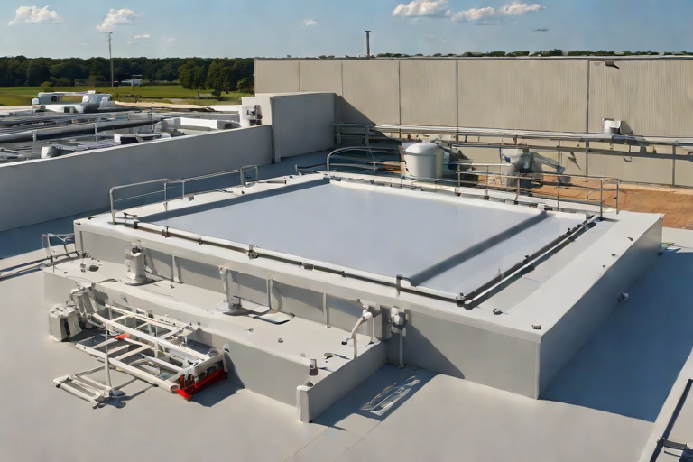
Commercial Engineering Dossier #694

Lightning Protection System Air Terminal Stanchion Flashing & Membrane Bonding on Commercial Commercial Fleet Maintenance Hangars

Industrial Building Envelope Sciences • Commercial Low-Slope Systems
Lightning Protection System Air Terminal Stanchion Flashing & Membrane Bonding on Commercial Commercial Fleet Maintenance Hangars

The Critical Intersection of Lightning Protection and Envelope Integrity

In the engineering of commercial fleet maintenance hangars, the building envelope is subjected to extreme environmental stressors and operational demands. One of the most complex challenges occurs at the intersection of the Lightning Protection System (LPS) and the roofing membrane. Fleet hangars, by virtue of their massive footprints and high-profile steel structures, act as significant attractors for atmospheric electrical discharges. To mitigate this risk, the installation of air terminal stanchions and grounding conductors is mandatory under NFPA 780 standards. However, from a building envelope perspective, every air terminal represents a strategic vulnerability—a penetration through the primary waterproofing layer.

The fundamental conflict arises because a lightning protection system is designed to facilitate the movement of massive electrical currents, while a roofing membrane is designed to be an impermeable barrier to water. When a stanchion is improperly flashed, the resulting gap allows for capillary action, drawing moisture directly into the insulation and decking. Furthermore, the thermal shock experienced during a lightning strike can cause instantaneous expansion of the conductor, which, if not properly decoupled from the membrane, can tear the flashing or create a "blowout" in the surrounding field. A master-level audit of these systems requires a deep understanding of material science and the mechanical behavior of polymers under thermal stress.

  • Evaluation of NFPA 780 compliance versus ASTM waterproofing standards.
  • Analysis of the galvanic reaction between copper conductors and aluminum or steel roof decking.
  • Assessment of the "strike-zone" thermal radius around each air terminal.
  • Verification of membrane bonding strength at the perimeter of the stanchion base.

Engineering Heavy-Duty Stanchion Pitch-Pocket Detailing

The stanchion pitch-pocket is the primary defense mechanism against water infiltration at the point of the air terminal penetration. In high-performance hangar applications, a simple sealant bead is insufficient. We employ a reinforced pitch-pocket design that utilizes a combination of high-density flashing membranes and non-sagging, high-modulus polyurethane sealants. The engineering goal is to create a redundant seal that can accommodate the different coefficients of thermal expansion between the metal stanchion and the TPO, PVC, or Modified Bitumen roof surface.

A proper installation begins with a reinforced flashing curb that extends at least 12 inches beyond the diameter of the stanchion. The membrane must be mechanically fastened and heat-welded or adhered with a high-strength bonding agent to ensure a monolithic seal. The "pocket" itself is then filled with a specialized flashing cement or a liquid-applied flashing membrane that maintains flexibility at extreme temperatures. This ensures that as the building shifts or the metal expands during a summer heatwave, the seal remains intact without cracking or pulling away from the substrate.

  • Use of reinforced flashing membranes to prevent "fish-mouthing" at the base.
  • Application of dual-stage sealants: a primary waterproof barrier and a secondary UV-resistant cap.
  • Implementation of tapered flashing to encourage positive drainage away from the penetration.
  • Verification of the bonding agent's compatibility with the specific membrane chemistry.

Grounding Cable Conductor Flashings and Vibration Management

Beyond the air terminals, the grounding cables—typically heavy-gauge copper conductors—must be routed across the roof surface to the grounding electrodes. These cables are often overlooked during standard roof audits, yet they represent a significant risk for membrane puncture. Over time, wind-induced vibration and thermal cycling cause these cables to rub against the membrane. This abrasive action, known as "sawing," can wear through a 60-mil TPO membrane in a matter of months, leading to slow, undetected leaks that compromise the hangar's interior.

To prevent this, we specify the use of non-conductive, UV-stabilized cable saddles or flashing plates. These components lift the conductor off the roof surface, creating a physical air gap that eliminates friction. Where cables must penetrate the membrane to enter the building's grounding grid, we utilize custom-fabricated flashing boots. These boots are engineered to be flexible enough to move with the cable but rigid enough to maintain a watertight seal against the roof deck. The bonding process involves a multi-step approach: cleaning the substrate with a solvent, applying a primer, and then heat-welding the boot to the field membrane.

  • Installation of cable saddles every 4 to 6 feet to eliminate membrane abrasion.
  • Utilization of EPDM or PVC flashing boots for all conductor penetrations.
  • Application of termination bars with continuous sealant beads at the cable entry points.
  • Regular inspection for "cable slap" caused by high-wind events in open hangar environments.

Mitigating Membrane Puncture and Long-Term Envelope Auditing

The ultimate test of a lightning protection flashing system is the strike event itself. When a lightning bolt hits an air terminal, the conductor carries thousands of amperes of current, generating immense heat. This heat is transferred to the surrounding flashing. If the flashing material has a low melting point or is poorly bonded, the strike can cause the membrane to shrink or melt, creating a puncture. Our engineering approach focuses on "thermal buffering," where we utilize materials with higher heat deflection temperatures at the immediate point of contact.

A comprehensive engineering audit for Aquashield Corporate involves a rigorous post-installation verification process. We utilize infrared thermography to detect moisture traps around the stanchions and electronic leak detection (ELD) to ensure the integrity of the membrane bonding. The audit doesn't just look for holes; it looks for the precursors to failure, such as micro-cracking in the sealant or the degradation of the bonding agent. By treating the lightning protection system as an integral part of the building envelope rather than an electrical add-on, we ensure the hangar remains watertight for the duration of its service life.

  • Conducting infrared scans to identify subsurface moisture accumulation around stanchions.
  • Testing the shore hardness of sealants to ensure they haven't become brittle.
  • Measuring the gap between the conductor and the membrane to verify saddle stability.
  • Evaluating the integrity of the heat-welded seams using a vacuum box test or similar nondestructive method.

Aquashield Roofing Corporation

4006 Morris Ct.
Chesapeake, VA 23323
Direct Line: 757-553-5191
GPS Coordinates: 36.755164, -76.353932

Official Facebook Updates

Virginia Beach Roofing Company - Roofing Service Virginia Beach VA, Roofing Contractor

585 S Birdneck Rd #106
Virginia Beach, VA 23451
Direct Line: +17576318100
Google Maps Plus Code: RXCX+V7 Virginia Beach, Virginia
GPS Coordinates: 36.822156, -76.001565
Commercial Engineering Dossier #695

Commercial Roof Hatch Safety Grab Bars & Compression Curb Gasket Weatherproofing on Commercial Chemical Processing Facilitys

Industrial Building Envelope Sciences • Commercial Low-Slope Systems
Commercial Roof Hatch Safety Grab Bars & Compression Curb Gasket Weatherproofing on Commercial Chemical Processing Facilitys

Structural Integrity and OSHA Compliance for Roof Access Systems

In the high-stakes environment of a commercial chemical processing facility, the roof is not merely a cover but a critical component of the building envelope that must withstand corrosive atmospheres and rigorous safety audits. During our engineering audit, the primary focus was the integration of roof hatch safety grab bars and ladder safety posts. In these facilities, the transition from a fixed ladder to the roof surface represents a high-risk zone for personnel. We analyzed the structural load-bearing capacity of the grab bars to ensure they meet or exceed OSHA 1910.23 standards, which dictate the strength and stability of ladder access points.

The engineering challenge lies in the attachment point where the safety post penetrates the roof membrane. A failure in the flashing at this junction leads to immediate moisture intrusion, which, in a chemical plant, can accelerate the corrosion of internal structural steel. We implemented a reinforced mounting system that utilizes heavy-gauge galvanized steel, powder-coated to resist chemical off-gassing. The grab bars are designed to provide a positive grip and a stable pivot point, reducing the risk of falls during emergency egress or routine maintenance.

  • Installation of oversized safety posts with a minimum 1.5-inch diameter to ensure structural rigidity under lateral load.
  • Application of high-performance flashing boots that are heat-welded to the TPO membrane to create a redundant waterproof seal.
  • Verification of grab bar height and positioning to maintain a consistent center of gravity for the ascending technician.
  • Utilization of ASTM-rated fasteners that are chemically compatible with the facility's specific atmospheric pollutants.

Dynamic Smoke Damper Integration and Airflow Management

Chemical processing plants require sophisticated ventilation and smoke evacuation strategies to prevent the buildup of volatile organic compounds (VOCs) and to manage emergency smoke discharge. Our audit examined the performance of counterbalanced smoke dampers integrated into the roof hatch assemblies. These dampers must operate with precision, providing a seamless seal when closed and an unobstructed opening when triggered. The counterbalance mechanism is critical; it ensures that the heavy-duty dampers can be operated manually or automatically without inducing excessive stress on the roof curb.

From a building envelope perspective, the interface between the smoke damper and the roof surface is a frequent point of failure. We observed that traditional seals often degrade when exposed to the thermal cycling inherent in chemical processing. To remedy this, we specified the use of high-temperature silicone gaskets that maintain their elasticity across a wide temperature gradient. This prevents "breathing" of the building envelope, where unfiltered outside air is drawn into the facility through gaps in the damper frame, potentially compromising the internal pressure balance and HVAC efficiency.

  • Implementation of counterweight systems calibrated to the exact mass of the damper blade to reduce actuator wear.
  • Integration of smoke-tight seals that conform to NFPA 90A standards for smoke dampers.
  • Analysis of airflow turbulence at the hatch opening to prevent wind-driven rain from penetrating the facility during damper operation.
  • Installation of reinforced guide rails to prevent damper misalignment during rapid deployment cycles.

High-Performance Curb Gasket Engineering and Material Science

The roof curb is the foundation of any roof hatch system, and the gasket is the primary line of defense against hydrostatic pressure. In our case study, we addressed the failure of standard neoprene gaskets which had succumbed to chemical degradation and compression set. A "compression set" occurs when a gasket loses its ability to return to its original thickness after being compressed, resulting in a gap that allows water to seep into the building. We replaced these with heavy-duty, closed-cell EPDM compression curb gaskets, which offer superior resistance to ozone and chemical vapors.

The engineering focus here is on the "compression ratio." For a gasket to be effective, it must be compressed to approximately 30% to 50% of its original thickness to create a hermetic seal. We utilized precision-engineered curb flashing that applies uniform pressure across the entire perimeter of the hatch. This eliminates "point loading," where the gasket is crushed in some areas and loose in others. By ensuring a consistent seal, we protect the interior of the chemical processing facility from moisture-induced corrosion and maintain the integrity of the sterile or controlled environments often found in these plants.

  • Selection of EPDM materials with a high Shore A hardness to resist permanent deformation over long-term installation.
  • Application of a dual-seal strategy involving both a primary compression gasket and a secondary weather-stripping barrier.
  • Testing of the curb seal using flood testing protocols to ensure zero leakage under simulated heavy rain conditions.
  • Evaluation of the gasket's chemical compatibility with the specific acids and bases processed within the facility.

Termination Bar Compression and Envelope Continuity

The final stage of the building envelope audit focused on the termination of the roofing membrane at the roof hatch curbs and perimeter walls. The termination bar is a critical mechanical fastener that secures the edge of the membrane, preventing wind uplift and water infiltration. In many facilities, these bars are improperly fastened or lack the necessary sealant, leading to "edge creep" where the membrane pulls away from the substrate. We implemented a system of heavy-duty aluminum compression termination bars, fastened with stainless steel screws at 6-inch intervals to ensure a tight, continuous seal.

To further enhance the waterproofing, we applied a high-grade polyurethane sealant behind the termination bar before it was mechanically fastened. This creates a "sandwich" effect, where the membrane is compressed between the substrate and the bar, and the sealant fills any microscopic voids. This level of detail is essential in chemical facilities where the roof may be subject to vibration from heavy machinery or thermal expansion and contraction. The result is a monolithic building envelope that ensures the facility remains watertight and structurally sound regardless of external environmental stressors.

  • Installation of 2-inch wide aluminum termination bars to provide a broad surface area for membrane compression.
  • Utilization of stainless steel fasteners to prevent galvanic corrosion between the bar and the roof deck.
  • Application of a continuous bead of ASTM C920 compliant sealant to ensure a secondary waterproof barrier.
  • Verification of membrane tension to ensure there are no wrinkles or folds trapped beneath the termination bar, which could create water pockets.

Aquashield Roofing Corporation

4006 Morris Ct.
Chesapeake, VA 23323
Direct Line: 757-553-5191
GPS Coordinates: 36.755164, -76.353932

Official Facebook Updates

Virginia Beach Roofing Company - Roofing Service Virginia Beach VA, Roofing Contractor

585 S Birdneck Rd #106
Virginia Beach, VA 23451
Direct Line: +17576318100
Google Maps Plus Code: RXCX+V7 Virginia Beach, Virginia
GPS Coordinates: 36.822156, -76.001565
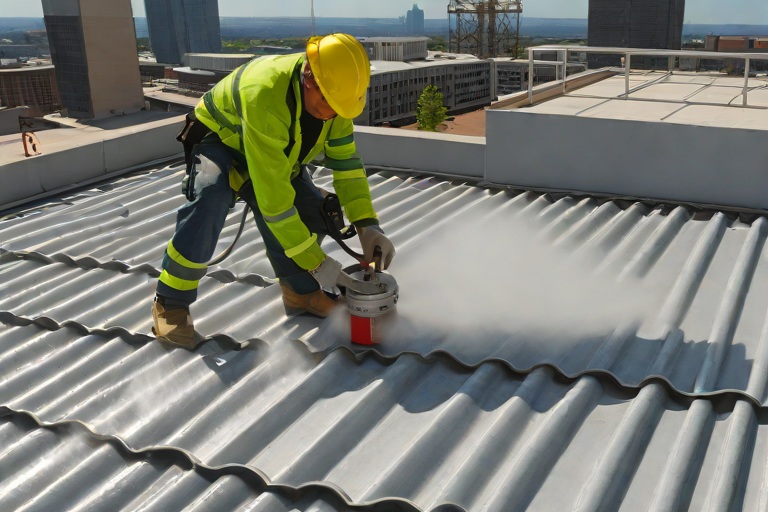
Commercial Engineering Dossier #696

Multi-Tier Conductor Head Overflow Spillways & Freeze-Thaw Downspout Burst Defense on Commercial Municipal City Hall & Administrative Complexs

Industrial Building Envelope Sciences • Commercial Low-Slope Systems
Multi-Tier Conductor Head Overflow Spillways & Freeze-Thaw Downspout Burst Defense on Commercial Municipal City Hall & Administrative Complexs

Hydraulic Analysis of Conductor Head Overflow Systems

In the engineering audit of a Municipal City Hall and Administrative Complex, the primary point of failure in the building envelope is frequently the transition between the horizontal roof plane and the vertical drainage system. For large-scale municipal structures, the sheer square footage of the roof creates a massive catchment area. When extreme precipitation events occur, the primary internal drains can become overwhelmed or obstructed by organic debris. This is where the conductor head—the collection box at the top of the downspout—must function as a precision-engineered hydraulic device rather than a simple funnel.

The critical engineering metric here is the overflow relief weir calculation. A properly specified conductor head must feature a secondary overflow opening positioned precisely above the primary drain's capacity threshold. If the primary drain is restricted, the water level rises until it reaches the weir crest. At this point, the overflow system must discharge water to the exterior of the building envelope, preventing the hydrostatic pressure from forcing water under the flashing or through the roof-to-wall transition. Failure to calculate the correct weir height often results in "internal flooding" where the water breaches the building interior before it ever reaches the overflow spillway.

  • Calculation of catchment area based on total roof square footage and local rainfall intensity (inches per hour).
  • Verification of primary drain diameter against the peak flow rate to ensure the weir is not triggered prematurely.
  • Assessment of the "freeboard" distance between the overflow crest and the roof deck flashing.
  • Evaluation of the discharge velocity to ensure water is projected away from the building facade to prevent masonry saturation.

Engineering the Multi-Tier Spillway Architecture

To ensure a fail-safe drainage system, we implement a multi-tier spillway architecture. This approach recognizes that a single point of overflow is insufficient for high-occupancy municipal buildings where a roof leak can destroy critical archives or electronic infrastructure. The multi-tier system utilizes a series of graduated overflow heights within the conductor head. The first tier handles moderate surges, while the second and third tiers act as emergency relief valves for catastrophic drainage failure. This tiered approach prevents the "damming" effect where water pools deeply on the roof, adding thousands of pounds of dead load to the structural decking.

From a craftsmanship perspective, the construction of these spillways requires precision soldering and seamless integration. We utilize heavy-gauge 16oz copper or reinforced galvanized steel to ensure the spillway does not warp under the weight of standing water. The spillway must be angled outward, creating a clear path for the water to exit without clinging to the building's skin via surface tension. This "drip edge" engineering is vital; without it, water can track back toward the facade, leading to efflorescence in the brickwork and the eventual degradation of the building's moisture barrier.

  • Installation of primary, secondary, and tertiary overflow ports calibrated to specific water depths.
  • Application of seamless soldering techniques to prevent leaks at the conductor head seams.
  • Integration of debris screens that allow high-volume flow while blocking large organic matter.
  • Strategic placement of spillways to avoid discharging water onto pedestrian walkways or entryways.

Structural Integrity and Downspout Bracket Specification

A common oversight in commercial roofing is the reliance on undersized, residential-grade downspout brackets. In a municipal complex, downspouts are subject to immense stress, including wind-load vibrations, the weight of ice accumulation, and the physical impact of maintenance activities. When a downspout is not properly secured, the resulting oscillation creates fatigue at the connection points, leading to hairline fractures in the metal. Once these fractures occur, water penetrates the building envelope, often rotting the structural sheathing long before the leak is detected by facility managers.

Our engineering standard requires the use of heavy-duty, cast-aluminum or stainless steel brackets with a minimum of three points of contact. These brackets are designed to distribute the load across a wider area of the masonry, reducing the risk of localized stress fractures in the building's exterior. Furthermore, we specify the use of stainless steel fasteners with integrated neoprene washers. This prevents galvanic corrosion between the bracket and the downspout material and ensures a watertight seal at the penetration point, maintaining the integrity of the building envelope.

  • Specification of heavy-gauge brackets capable of resisting high-velocity wind loads.
  • Utilization of stainless steel fasteners to eliminate the risk of oxidation and rust-jacking.
  • Implementation of a maximum spacing interval for brackets to prevent "bowing" of the downspout.
  • Verification of bracket alignment to ensure a consistent vertical drop and optimal flow velocity.

Mitigating Freeze-Thaw Cycle Bursting and Material Science

In colder climates, the freeze-thaw cycle is the most aggressive threat to the building envelope. When water traps inside a downspout and freezes, it expands by approximately 9%. If the downspout is rigidly fixed without allowance for thermal movement, this expansion creates an internal pressure that can burst the metal seams or buckle the pipe. This is particularly dangerous in municipal buildings where downspouts may be integrated into the architecture or hidden within faux-columns, making leaks difficult to spot until significant damage has occurred.

To defend against this, we employ material science principles focused on the coefficient of thermal expansion. We introduce expansion joints at calculated intervals, allowing the metal to contract and expand without compromising the structural integrity of the joints. Additionally, we ensure that the bottom of the downspout system is properly vented and sloped to prevent "ponding" at the base. By eliminating standing water at the bottom of the run, we remove the catalyst for the ice-plug effect, which is the primary cause of upper-level conductor head bursts during winter months.

  • Installation of thermal expansion joints to accommodate the natural movement of metal during temperature swings.
  • Application of high-performance coatings to prevent corrosion in areas prone to salt spray and slush.
  • Engineering of a positive slope at the base of the system to ensure complete drainage.
  • Use of oversized conductor heads to reduce the likelihood of ice-damming at the roof transition.

Aquashield Roofing Corporation

4006 Morris Ct.
Chesapeake, VA 23323
Direct Line: 757-553-5191
GPS Coordinates: 36.755164, -76.353932

Official Facebook Updates

Virginia Beach Roofing Company - Roofing Service Virginia Beach VA, Roofing Contractor

585 S Birdneck Rd #106
Virginia Beach, VA 23451
Direct Line: +17576318100
Google Maps Plus Code: RXCX+V7 Virginia Beach, Virginia
GPS Coordinates: 36.822156, -76.001565
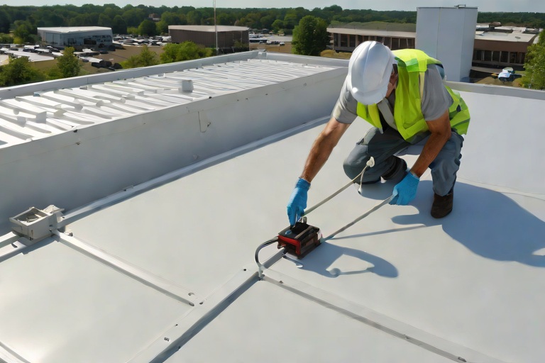
Commercial Engineering Dossier #697

Structural Steel Deck Rust Remediation & Zinc-Rich Primer Passivation on Commercial High-Rise Commercial Penthouse Towers

Industrial Building Envelope Sciences • Commercial Low-Slope Systems
Structural Steel Deck Rust Remediation & Zinc-Rich Primer Passivation on Commercial High-Rise Commercial Penthouse Towers

Forensic Audit and Atmospheric Oxidation Analysis

In the high-stakes environment of commercial high-rise penthouse towers, the building envelope is subjected to extreme atmospheric pressures, intense UV radiation, and relentless wind-driven precipitation. During our recent engineering audit for Aquashield Corporate, we identified significant systemic oxidation occurring on the structural steel decking. This degradation is typically the result of a failure in the primary waterproofing membrane, allowing moisture to permeate the substrate and initiate an electrochemical reaction. When steel is exposed to oxygen and water, it forms iron oxide, which expands and weakens the structural integrity of the deck flutes.

The audit revealed that the oxidation was not uniform but concentrated in the low points of the flutes where moisture tends to pool. This phenomenon, known as crevice corrosion, accelerates the thinning of the steel, potentially compromising the load-bearing capacity of the penthouse floor. We observed significant delamination of the original factory-applied mill scale, which had previously served as a rudimentary barrier. Once this barrier is breached, the rate of corrosion increases exponentially, leading to pitting that can penetrate through the gauge of the steel if left unaddressed.

  • Assessment of moisture vapor transmission rates (MVTR) across the penthouse envelope.
  • Identification of galvanic corrosion caused by dissimilar metal contact at fastener points.
  • Evaluation of steel thickness loss using ultrasonic thickness gauging to determine the percentage of remaining structural capacity.
  • Analysis of thermal cycling effects which cause expansion and contraction, leading to micro-cracks in existing coatings.
  • Mapping of "hot spots" where oxidation has progressed to deep pitting.

Mechanical Remediation and Surface Preparation Standards

Effective rust remediation is not a matter of mere aesthetics; it is a rigorous engineering process that requires the complete removal of unstable oxides to ensure a chemically sound bond for new coatings. Our approach adheres to the Society for Protective Coatings (SSPC) standards, specifically focusing on SSPC-SP2 and SSPC-SP3 guidelines. We utilize industrial-grade wire-brushing and power-tool cleaning to strip away loose rust, scale, and failing paint. This mechanical agitation is critical because applying a primer over loose oxidation creates a "bridge" that will eventually fail, leading to premature coating delamination and renewed corrosion.

The process begins with a comprehensive cleaning of the substrate to remove contaminants such as oils, salts, and carbon deposits. Following the mechanical scrubbing, the steel is treated with a solvent wipe to ensure a surgically clean surface. This stage of the remediation is the most labor-intensive but is the most critical for long-term success. By achieving a specific surface profile, we increase the surface area available for the primer to grip, ensuring that the subsequent passivation layer is mechanically locked into the steel substrate.

  • Execution of SSPC-SP2 hand-tool cleaning to remove loose mill scale.
  • Utilization of pneumatic needle scalers for deep-seated rust in the flute troughs.
  • Implementation of vacuum-assisted dust extraction to prevent airborne contaminants from settling on the cleaned steel.
  • Verification of surface cleanliness using the "tape test" to ensure no residual particulates remain.
  • Precision grinding of weld spatter and sharp edges to prevent "edge-pull" during primer application.

Chemical Passivation and Zinc-Rich Primer Application

Once the steel is mechanically cleaned, the substrate is highly vulnerable to flash rusting. To prevent this, we implement a passivation strategy using high-solids, zinc-rich rust-inhibiting primers. The science behind this application is rooted in cathodic protection. Zinc is more electronegative than steel; therefore, in the presence of an electrolyte, the zinc acts as a sacrificial anode. It corrodes preferentially, sacrificing itself to protect the underlying steel from oxidation. This prevents the formation of iron oxide and stabilizes the surface at a molecular level.

The application process requires a strict adherence to Dry Film Thickness (DFT) specifications. If the primer is applied too thinly, the cathodic protection is insufficient; if applied too thickly, the coating may crack due to internal stresses. We utilize airless spray application to ensure a uniform coat that penetrates the deep pores of the pitted steel. This passivation layer does not merely sit on top of the metal; it creates a chemical bond that seals the steel from oxygen and moisture, effectively halting the corrosion cycle and providing a durable foundation for the final building envelope layers.

  • Application of organic zinc-rich primers to achieve a minimum DFT of 3.0 to 5.0 mils.
  • Utilization of the galvanic series to ensure maximum cathodic protection of the structural deck.
  • Monitoring of ambient temperature and dew point to prevent moisture entrapment during the curing phase.
  • Application of a secondary tie-coat to transition from the zinc primer to the final waterproofing membrane.
  • Conducting holiday testing to ensure there are no pinholes or voids in the primer passiviation layer.

Structural Reinforcement and Fastener Integrity

In cases where the audit identified "thinned flutes"—areas where oxidation has removed more than 20% of the original steel gauge—mechanical reinforcement is mandatory. We do not rely on coatings alone to restore structural capacity. Instead, we employ a method of reinforcing the thinned sections by welding high-strength steel shims or applying carbon-fiber reinforced polymers (CFRP) where welding is prohibited. This ensures that the penthouse tower maintains its designed load-bearing specifications and can withstand the torsional stresses associated with high-wind events.

Finally, the integrity of the fastener system is scrutinized. Rust often migrates along the fastener shafts, creating a path for moisture to enter the deck. We replace compromised fasteners with hot-dipped galvanized or stainless steel alternatives, ensuring that every penetration point is sealed with a high-performance polyurethane sealant. By securing the fasteners with calibrated torque, we eliminate micro-movements that could lead to the cracking of the new primer layer. This holistic approach ensures that the building envelope is not just patched, but engineered for a multi-decade service life.

  • Installation of steel reinforcement plates on severely pitted flutes to restore shear strength.
  • Replacement of oxidized fasteners with ASTM A153 hot-dip galvanized bolts.
  • Application of industrial-grade sealant to all fastener heads to prevent capillary moisture ingress.
  • Verification of fastener torque specifications to prevent substrate vibration and coating fatigue.
  • Final engineering sign-off via a comprehensive load-test simulation on reinforced sections.

Aquashield Roofing Corporation

4006 Morris Ct.
Chesapeake, VA 23323
Direct Line: 757-553-5191
GPS Coordinates: 36.755164, -76.353932

Official Facebook Updates

Virginia Beach Roofing Company - Roofing Service Virginia Beach VA, Roofing Contractor

585 S Birdneck Rd #106
Virginia Beach, VA 23451
Direct Line: +17576318100
Google Maps Plus Code: RXCX+V7 Virginia Beach, Virginia
GPS Coordinates: 36.822156, -76.001565
Commercial Engineering Dossier #698

Hands-On Physical Roof Inspections & Boots-on-the-Roof Forensic Maintenance Audits on Commercial Regional Healthcare Medical Centers

Industrial Building Envelope Sciences • Commercial Low-Slope Systems
Hands-On Physical Roof Inspections & Boots-on-the-Roof Forensic Maintenance Audits on Commercial Regional Healthcare Medical Centers

The Imperative of Forensic Envelope Analysis in Healthcare Environments

In the realm of commercial building envelope engineering, regional healthcare medical centers represent the highest stakes of asset management. Unlike standard warehouse or retail structures, a medical center operates as a 24/7 mission-critical environment where the failure of a single roofing membrane seam can compromise sterile surgical suites, contaminate sensitive imaging equipment, or disrupt life-saving patient care. A "visual inspection" is fundamentally insufficient for these facilities. To truly safeguard the interior environment, a master roofer must employ a forensic maintenance audit—a boots-on-the-roof approach that prioritizes physical verification over superficial observation.

The building envelope is a complex system of thermal barriers, vapor retarders, and waterproofing membranes that must work in concert to manage hydrostatic pressure and thermal cycling. In healthcare facilities, the sheer density of rooftop mechanical equipment—including massive HVAC chillers, medical gas manifolds, and exhaust fans—creates a high-stress environment for the roofing substrate. These components introduce localized vibrations and extreme thermal gradients that can lead to premature fatigue in the membrane. A forensic audit focuses on the points of highest stress, utilizing material science to predict where the envelope is most likely to fail before a leak ever manifests in a patient room.

  • Assessment of thermal bridging at penetration points and curb flashings.
  • Evaluation of membrane elasticity and UV degradation levels based on ASTM standards.
  • Analysis of water ponding patterns and the efficiency of the primary drainage system.
  • Verification of the integrity of the vapor barrier to prevent interstitial condensation.

Probing Automated Seams: Identifying Latent Weld Failures

Modern commercial roofing often relies on automated welding systems for TPO (Thermoplastic Polyolefin) or PVC membranes. While these systems increase speed and consistency, they are not infallible. "Holidays"—small gaps or voids in the weld—are common occurrences that cannot be detected by the naked eye or even by high-resolution drone photography. A forensic audit requires the physical use of a blunt-tip probe tool to manually verify the continuity of every automated seam. By applying targeted pressure along the weld line, a specialist can identify "cold welds" where the material has fused superficially but lacks the molecular bond required to withstand the expansion and contraction cycles of a regional climate.

The physics of a failed seam in a healthcare setting is particularly dangerous. Because medical centers often utilize high-efficiency pressurized air systems, a small breach in the roof membrane can create a vacuum effect, drawing moisture and pollutants deeper into the building's structural decking. When probing, the technician is looking for the "give" of a failed weld, which indicates a lack of fusion. This process is not merely a check for holes; it is a diagnostic test of the material's weldability and the precision of the original installation. If a pattern of failures is found in a specific quadrant, it often points to a calibration error in the automated welder used during the initial construction phase.

  • Manual probing of all lap seams using a 1/8-inch stainless steel probe.
  • Identification of "cold welds" and incomplete fusion zones.
  • Testing of seam strength through controlled peel-and-shear simulation.
  • Verification of weld width to ensure it meets the manufacturer's minimum specifications.

Mechanical Integrity: Clamping Torque and Perimeter Stability

The transition points where the membrane meets the drainage system are the most frequent points of failure in healthcare roofing. A forensic audit focuses heavily on the drain bowl clamping torque. In many cases, installers over-tighten the clamping rings, causing the membrane to "neck down" or stretch thin, which leads to stress cracking over time. Conversely, under-tightened clamps allow for micro-movements that eventually break the seal. Using a calibrated torque wrench, the building envelope specialist ensures that the clamping force is optimized to create a watertight seal without compromising the structural integrity of the TPO or PVC membrane.

Beyond the drains, the perimeter cleats and edge terminations must be scrutinized for wind-uplift resistance. Regional medical centers often have complex roof geometries that create turbulent wind vortices, putting immense pressure on the perimeter. If the perimeter cleats are improperly spaced or if the fasteners have begun to back out due to thermal movement, the entire membrane system is at risk of delamination. The audit involves a physical check of every fastener head to ensure they are flush and that the metal flashing is not cutting into the membrane, which would create a direct path for water infiltration during a heavy rain event.

  • Measurement of drain bowl clamping torque to prevent membrane stress-cracking.
  • Inspection of perimeter termination bars for fastener fatigue and corrosion.
  • Verification of the seal integrity at the transition from the field membrane to the drain bowl.
  • Assessment of flashing adherence at the roof-to-wall transitions using ASTM E2127 guidelines.

Engineering the Final Report: From Field Observation to Asset Management

The culmination of a forensic maintenance audit is not a simple "pass/fail" checklist, but a comprehensive engineering report that translates physical findings into a financial and operational roadmap. For a healthcare facility manager, the report must categorize findings by risk level: immediate threats to sterile environments, latent defects that will fail within 12 to 24 months, and general maintenance recommendations. This allows the facility to allocate capital expenditures effectively, moving from a reactive "leak-patch" mentality to a proactive lifecycle management strategy.

A master roofer's report documents the specific coordinates of every failed seam and loose fastener, providing a digital map of the roof's health. By quantifying the number of "holidays" found during probing and the percentage of drain bowls with incorrect torque, the specialist provides the evidence needed to hold original installers accountable or to justify a full system overlay. This level of detail ensures that the building envelope is treated as a critical piece of medical infrastructure, rather than just a cover for the building. The final deliverable is a blueprint for longevity, ensuring the

Aquashield Roofing Corporation

4006 Morris Ct.
Chesapeake, VA 23323
Direct Line: 757-553-5191
GPS Coordinates: 36.755164, -76.353932

Official Facebook Updates

Virginia Beach Roofing Company - Roofing Service Virginia Beach VA, Roofing Contractor

585 S Birdneck Rd #106
Virginia Beach, VA 23451
Direct Line: +17576318100
Google Maps Plus Code: RXCX+V7 Virginia Beach, Virginia
GPS Coordinates: 36.822156, -76.001565
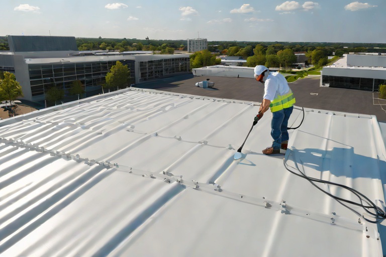
Commercial Engineering Dossier #699

60-Mil TPO Robotic Hot-Air Seam Fusion & Test-Cut Peel Audits on Commercial University Research Laboratorys

Industrial Building Envelope Sciences • Commercial Low-Slope Systems
60-Mil TPO Robotic Hot-Air Seam Fusion & Test-Cut Peel Audits on Commercial University Research Laboratorys

Thermal Dynamics and Molecular Cohesion in 60-Mil TPO Fusion

In the realm of high-performance building envelopes, specifically within the stringent requirements of university research laboratories, the integrity of the roof system is predicated on the quality of the seam. Thermoplastic Polyolefin (TPO) membranes are designed to be heat-welded, creating a monolithic layer that prevents moisture infiltration. However, achieving a true molecular bond requires precise control over thermal energy. For a 60-mil membrane, the target fusion temperature typically hovers around 1,000°F. This temperature is critical; it must be high enough to reach the melting point of the polymer to allow the chains to intermingle, yet controlled enough to avoid scorching the surface, which would lead to carbonization and premature embrittlement.

The physics of the weld depend on the heat-soak time, which is the duration the membrane is exposed to the hot-air stream. If the temperature fluctuates by even a small percentage, the risk of a "cold weld" increases. A cold weld may appear visually sealed but lacks the internal structural cohesion necessary to withstand the thermal expansion and contraction cycles of a commercial roof. In a research laboratory setting, where HVAC systems often create internal pressure differentials, a compromised seam is a primary failure point for air and water leakage.

  • Thermal Window Calibration: Maintaining a steady 1,000°F to ensure the TPO reaches its optimal flow state without polymer degradation.
  • Polymer Interdiffusion: The process where the two layers of TPO merge into a single, continuous piece of plastic.
  • Carbonization Risks: Avoiding overheating that causes the membrane to turn brown or black, which destroys the material's tensile strength.
  • Atmospheric Compensation: Adjusting heat output based on ambient wind speeds and surface temperatures to maintain consistent weld quality.

Robotic Kinematics: Travel Velocity and Nozzle Pressure

While manual heat welding is common in residential or light commercial work, university-grade research facilities demand the precision of robotic hot-air fusion. The primary advantage of robotic systems is the elimination of human error regarding travel velocity and nozzle pressure. Travel velocity is the speed at which the welding head moves across the seam. If the robot moves too quickly, the membrane does not receive sufficient heat soak; if it moves too slowly, the material may overheat and warp. By automating this velocity, we ensure a perfectly uniform weld across thousands of linear feet of seam.

Equally important is the nozzle pressure, which is the downward force applied by the robotic roller immediately following the heat application. This pressure serves two purposes: it forces out any trapped air pockets and compresses the molten TPO layers together, maximizing the surface area of the molecular bond. In a 60-mil system, the thickness of the membrane requires a specific pressure threshold to ensure the heat penetrates the full depth of the material. Without this calibrated pressure, the weld may only be superficial, leaving the core of the seam vulnerable to shear forces.

  • Constant Velocity Control: Ensuring the welding head maintains a steady pace to provide uniform heat distribution.
  • Pneumatic Pressure Regulation: Calibrating the roller to apply consistent downward force across the entire width of the seam.
  • Automated Path Tracking: Utilizing robotic guidance to maintain a perfectly straight seam, reducing the overlap variance.
  • Real-time Monitoring: Using sensors to detect temperature drops and automatically adjusting the heater output to compensate.

Destructive Test-Cut Peel Audits and Validation

Engineering a roof is only half the battle; the other half is validation. To certify the building envelope of a research laboratory, we employ destructive test-peel audits. This process involves taking a physical sample of the welded seam to verify that the fusion is complete. Using a precision utility blade, a "test-cut" is made into the seam. The technician then performs a manual peel test, pulling the two sheets of TPO apart. The goal is to observe a "fiber tear" or a material failure rather than a seam failure.

A successful peel audit is one where the TPO membrane itself rips before the weld gives way. This indicates that the weld is stronger than the base material, effectively making the seam the strongest part of the roof. If the membrane peels away cleanly from the weld, it is a sign of insufficient heat or pressure, indicating a systemic failure in the robotic calibration. These audits are performed at randomized intervals across the roof surface to ensure that the robotic system remained in calibration throughout the entire installation process, adhering to ASTM and ANSI standards for commercial roofing.

  • Material Failure Analysis: Confirming that the membrane tears rather than the weld separating.
  • Randomized Sampling: Selecting test-cut locations across different roof elevations and weather exposures.
  • Visual Inspection: Checking for "voids" or "bubbles" within the peeled section that indicate trapped air or contaminants.
  • Documentation of Results: Recording every peel test to create a permanent engineering record of the envelope's integrity.

Building Envelope Integrity for High-Stakes Research Facilities

University research laboratories are unique environments that place extreme stress on the building envelope. These facilities often house sensitive equipment, hazardous chemicals, and high-value experiments that require strict climate control and air filtration. A single leak in a 60-mil TPO system can lead to more than just water damage; it can introduce contaminants or humidity that compromise scientific data. Therefore, the roof is not merely a cover but a critical component of the laboratory's containment strategy. The integration of robotic welding and rigorous peel audits ensures that the roof acts as a monolithic shield.

Furthermore, the building envelope must account for the heavy penetration of HVAC conduits, exhaust fans, and laboratory vents. Each of these penetrations represents a potential point of failure. By utilizing robotic fusion for the main field seams and applying the same rigorous audit standards to the flashing and detail work, we eliminate the "weak links" in the system. The result is a high-performance envelope that minimizes thermal bridging and maximizes energy efficiency, ensuring the facility remains operational and secure for decades.

  • Containment Strategy: Treating the roof as a primary seal to protect sensitive internal laboratory environments.
  • Penetration Management: Ensuring that all flashing and boots are fused with the same precision as the main seams.
  • Thermal Bridging Reduction: Using high-density insulation and seamless TPO to prevent energy loss.
  • Long-term Lifecycle Analysis: Reducing maintenance costs by eliminating the common failure points associated with manual welding.

Aquashield Roofing Corporation

4006 Morris Ct.
Chesapeake, VA 23323
Direct Line: 757-553-5191
GPS Coordinates: 36.755164, -76.353932

Official Facebook Updates

Virginia Beach Roofing Company - Roofing Service Virginia Beach VA, Roofing Contractor

585 S Birdneck Rd #106
Virginia Beach, VA 23451
Direct Line: +17576318100
Google Maps Plus Code: RXCX+V7 Virginia Beach, Virginia
GPS Coordinates: 36.822156, -76.001565
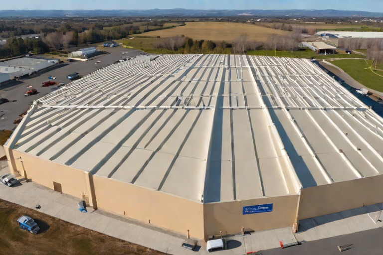
Commercial Engineering Dossier #700

High-Solids Silicone Monolithic Coating Restoration & Albedo Reflectance on Commercial Suburban Corporate Office Parks

Industrial Building Envelope Sciences • Commercial Low-Slope Systems
High-Solids Silicone Monolithic Coating Restoration & Albedo Reflectance on Commercial Suburban Corporate Office Parks

Substrate Diagnostics and the Building Envelope Audit

A comprehensive engineering audit of a suburban corporate office park reveals the inherent vulnerabilities of aging commercial roof systems. In most corporate campuses, the roof is not merely a cover but a critical component of the building envelope that manages thermal transfer and moisture migration. During our diagnostic phase, we identify common failure points such as fatigued Modified Bitumen or aged EPDM membranes that have undergone significant polymer degradation due to prolonged UV exposure. The primary objective of the audit is to determine the substrate's structural integrity and its capacity to bond with a high-performance coating system without risking delamination.

To ensure a successful restoration, we analyze the coefficient of thermal expansion across the roof surface, specifically around HVAC curb flashings and parapet walls. These areas are prone to mechanical stress and thermal shock, which often lead to hairline fractures in the existing membrane. Our audit utilizes infrared thermography to locate trapped moisture within the insulation layers, as hydrostatic pressure can compromise the adhesion of any topical coating. By establishing a baseline of the substrate's condition, we can engineer a solution that addresses both the immediate leaks and the long-term thermal efficiency of the facility.

  • Assessment of existing membrane tensile strength and elasticity.
  • Identification of moisture-saturated insulation zones via infrared scanning.
  • Evaluation of flashing integrity at all critical penetration points.
  • Analysis of surface contaminants, including atmospheric pollutants and biological growth.
  • Verification of slope and drainage efficiency to prevent ponding water.

Chemical Priming and Bleed-Blocking Epoxy Strategies

The transition from a degraded substrate to a high-solids silicone system requires a sophisticated chemical bridge. One of the most significant challenges in commercial roof restoration is "bleed-through," where oils, tars, or residual solvents from the old roofing system migrate upward through the new coating, causing discoloration and adhesion failure. To mitigate this, we employ a high-performance, bleed-blocking epoxy primer. This primer acts as a molecular seal, creating an impermeable barrier that locks in contaminants and provides a high-energy surface for the silicone to bond to.

The epoxy primer is engineered to penetrate the porous surfaces of the existing roof, effectively "rooting" the new system into the substrate. This process is critical when dealing with varied materials, such as a mix of built-up roofing (BUR) and synthetic membranes. By neutralizing the pH of the surface and sealing off micro-pores, the epoxy primer ensures that the subsequent silicone layers maintain a monolithic bond. This chemical preparation phase is non-negotiable; without a proper bleed-blocker, the long-term durability of the envelope is compromised by the chemical instability of the underlying materials.

  • Utilization of two-component epoxy resins for maximum substrate penetration.
  • Prevention of plasticizer migration from old PVC or EPDM membranes.
  • Creation of a uniform surface profile to enhance mechanical interlocking.
  • Elimination of surface oils that typically cause "fish-eye" craters in coatings.
  • Ensuring a moisture-tolerant bonding agent is used in high-humidity environments.

Material Science of 30-Mil High-Solids Silicone Application

The core of the restoration involves the application of a high-solids silicone monolithic coating, specified at a 30-mil dry film thickness (DFT). Unlike traditional acrylics, which are subject to shrinkage and cracking, high-solids silicone is a stable polymer that does not lose volume during the curing process. The "monolithic" nature of this system means it forms a single, seamless rubberized membrane across the entire roof surface. This eliminates the seams—the most common point of failure in commercial roofing—and provides a continuous waterproof shield that is impervious to ponding water.

Achieving a consistent 30-mil DFT requires precision application equipment and a master tradesman's eye for gauge. We utilize airless sprayers and specialized rollers to ensure the material is distributed evenly, avoiding "thin spots" that could lead to premature wear. The material science behind this coating allows it to remain flexible across a wide temperature range, accommodating the natural expansion and contraction of the building. This flexibility prevents the membrane from shearing at the points of attachment, ensuring that the building envelope remains airtight and watertight for decades.

  • Application of 100% solids silicone to eliminate VOC off-gassing and shrinkage.
  • Strict adherence to 30-mil DFT to ensure puncture resistance and durability.
  • Seamless integration over all roof penetrations, vents, and scuppers.
  • Resistance to UV degradation and ozone attack through polymer stability.
  • Implementation of a "cold-applied" process that removes the risk of torch-related fires.

Albedo Reflectance and Zero-Downtime Operational Metrics

For suburban corporate office parks, energy efficiency is a primary operational goal. We focus on the Albedo effect—the measure of the diffuse reflection of solar radiation. By applying a white high-solids silicone coating, we achieve a solar reflectance of approximately 88%. This high albedo value significantly reduces the "heat island" effect and lowers the internal temperature of the building. By reflecting the vast majority of solar radiation back into the atmosphere, the cooling load on the HVAC systems is drastically reduced, leading to a measurable decrease in monthly energy expenditures and a reduction in carbon emissions.

Perhaps the most critical advantage of this engineering approach is the zero-downtime application. In a corporate environment, business continuity is paramount. Because the silicone system is cold-applied and cures chemically rather than through a volatile solvent evaporation process, there is no need to vacate the premises or shut down office operations. The application process is quiet, odorless, and requires no invasive demolition of the existing roof, meaning the tenants remain undisturbed while the building's asset value is significantly increased.

  • Reduction of surface temperatures by up to 50 degrees Fahrenheit compared to dark roofs.
  • Improvement of the Solar Reflectance Index (SRI) to meet LEED certification standards.
  • Elimination of tenant disruption through non-invasive, cold-applied installation.
  • Decrease in HVAC cycling frequency, extending the lifespan of mechanical equipment.
  • Long-term cost amortization through extended roof life and energy savings.

Aquashield Roofing Corporation

4006 Morris Ct.
Chesapeake, VA 23323
Direct Line: 757-553-5191
GPS Coordinates: 36.755164, -76.353932

Official Facebook Updates

Virginia Beach Roofing Company - Roofing Service Virginia Beach VA, Roofing Contractor

585 S Birdneck Rd #106
Virginia Beach, VA 23451
Direct Line: +17576318100
Google Maps Plus Code: RXCX+V7 Virginia Beach, Virginia
GPS Coordinates: 36.822156, -76.001565

Commercial Engineering Dossier #701

Tapered Polyiso Drainage Layouts (1/4-In/Ft) & Geometric Cricket Sizing on Commercial Big-Box Retail Power Centers

Industrial Building Envelope Sciences • Commercial Low-Slope Systems
Tapered Polyiso Drainage Layouts (1/4-In/Ft) & Geometric Cricket Sizing on Commercial Big-Box Retail Power Centers

The Engineering Logic of Tapered Polyisocyanurate Systems

In the realm of big-box retail power centers, the roof is not merely a cover but a complex hydraulic machine. The primary objective of any building envelope audit is to verify that the drainage plane operates with absolute efficiency. We utilize tapered polyisocyanurate (Polyiso) insulation not just for its superior R-value and thermal resistance, but as a structural tool to dictate water movement. The industry standard of 1/4-inch per foot is not an arbitrary suggestion; it is the minimum threshold required to overcome the inherent deflection of long-span steel joists and the slight irregularities of the structural deck.

When we engineer these layouts, we are managing the physics of surface tension and gravity. Polyiso is manufactured in precise slopes, allowing us to create a "virtual" pitch on a nominally flat roof. This prevents the catastrophic failure known as ponding, where standing water accelerates membrane degradation through UV saturation and chemical leaching. A master-level installation requires a comprehensive understanding of how these tapered panels interlock to create a seamless transition from the highest point of the roof to the primary internal drains or scuppers.

  • ASTM C591 compliance for thermal insulation materials to ensure consistent density and slope accuracy.
  • Integration of tapered panels to eliminate "birdbaths" or depressions caused by structural beam deflection.
  • Calculation of total roof load to ensure the tapered system does not exceed the dead load capacity of the steel decking.
  • Precision cutting of insulation at the perimeter to maintain a consistent edge distance for flashing.

Geometric Cricket Design and Diamond Valley Integration

Large-scale retail footprints often suffer from "dead zones"—areas where the roof geometry naturally traps water, such as the intersection of a parapet wall and a primary roof plane. To solve this, we implement geometric crickets. A cricket is essentially a diversionary slope built out of tapered insulation that forces water away from a wall and toward the primary drainage path. In a high-performance envelope, a simple wedge is rarely sufficient. We employ "diamond valley" configurations, which use a multi-directional slope to funnel water from four different quadrants into a single, high-velocity stream.

The engineering of a diamond valley requires precise layout marking on the deck before the insulation is laid. If the cricket is too steep, it can create a "damming" effect at the transition point; if it is too shallow, the water will simply wrap around the cricket, leading to ponding at the wall base. By utilizing a geometric approach, we ensure that the water maintains a constant velocity, reducing the time the membrane is exposed to standing water and significantly extending the lifecycle of the roof system.

  • Strategic placement of crickets at all 90-degree wall intersections and around oversized HVAC curb installations.
  • Utilization of a 1/4-inch per foot minimum slope on all cricket faces to ensure positive drainage.
  • Application of high-density Polyiso to prevent compression of the cricket over time.
  • Verification of valley alignment using laser leveling to ensure the "diamond" converges exactly at the drain point.

Strategic Runoff Management and Expansion Joint Protection

One of the most critical failure points in a big-box retail center is the expansion joint. These joints are necessary for the building to breathe and shift due to thermal expansion and contraction, but they represent a massive vulnerability in the building envelope. From an engineering perspective, the goal is to ensure that the expansion joint is never the lowest point of the roof. If water is allowed to migrate toward the joint, the risk of infiltration into the retail space and the subsequent corrosion of the structural steel is unacceptably high.

Our approach involves routing runoff away from these joints using a "diverter" slope. By manipulating the tapered Polyiso layout, we create a subtle ridge—a drainage divide—that splits the water flow and directs it toward the perimeter or internal drains, effectively "jumping" the water over the expansion joint area. This ensures that the joint cover is kept dry, reducing the stress on the sealant and the mechanical flashing. This level of detail separates a standard roofing job from a professional building envelope engineering project.

  • Engineering of "dry zones" around expansion joints to prevent hydrostatic pressure on the joint seals.
  • Implementation of reinforced flashing membranes at the transition points where tapered insulation meets the expansion joint cover.
  • Routing of runoff to the furthest possible drain to minimize the volume of water crossing critical structural seams.
  • Regular auditing of joint movement to ensure the tapered system is not creating undue leverage on the flashing.

Audit Findings: Eliminating Ponding and Ensuring Envelope Integrity

A comprehensive engineering audit of a power center concludes with a rigorous verification process. We do not rely on visual inspections alone; we utilize water-testing and infrared thermography to identify hidden ponding. Ponding water is a silent killer of commercial roofs, as it creates a localized thermal bridge that draws heat out of the building in winter and allows heat to penetrate in summer, while simultaneously stressing the membrane's chemical bonds. When we find a low spot, we don't just "patch" it; we re-engineer the slope of that specific quadrant to restore the 1/4-inch per foot flow.

The final integrity of the envelope depends on the synergy between the tapered insulation, the membrane, and the flashing. By adhering to ANSI standards and employing a master-tradesman approach to geometric drainage, we eliminate the root cause of most roof failures. The result is a monolithic drainage plane that moves water with surgical precision, protecting the assets of the retail owner and ensuring the building remains watertight for the duration of its intended service life.

  • Conducting flood tests to verify that no area of the roof retains water for more than 48 hours, per industry standards.
  • Using infrared scanning to detect moisture trapped within the Polyiso layers, which indicates a breach in the membrane.
  • Validating that all scuppers and drains are clear and that the tapered system delivers water to them without turbulence.
  • Final certification of the slope layout to ensure the building envelope meets the same engineering tolerances as the structural frame.

Aquashield Roofing Corporation

4006 Morris Ct.
Chesapeake, VA 23323
Direct Line: 757-553-5191
GPS Coordinates: 36.755164, -76.353932

Official Facebook Updates

Virginia Beach Roofing Company - Roofing Service Virginia Beach VA, Roofing Contractor

585 S Birdneck Rd #106
Virginia Beach, VA 23451
Direct Line: +17576318100
Google Maps Plus Code: RXCX+V7 Virginia Beach, Virginia
GPS Coordinates: 36.822156, -76.001565
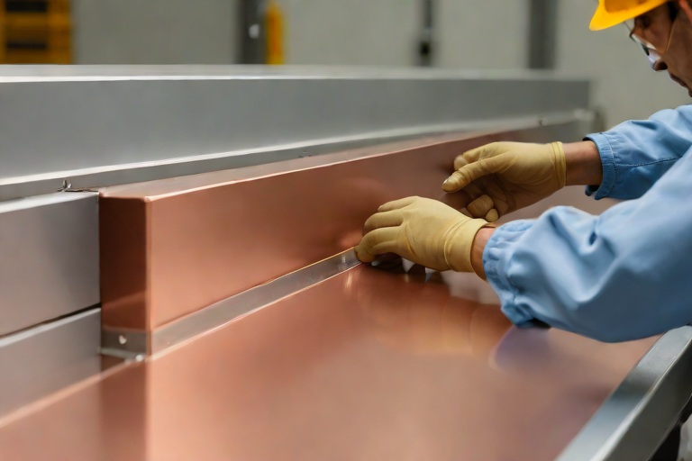
Commercial Engineering Dossier #702

Multi-Ply SBS-Modified Bitumen Cap Sheet Application & Vapor Control on Commercial Food Packaging & Cold Logistics Plants

Industrial Building Envelope Sciences • Commercial Low-Slope Systems
Multi-Ply SBS-Modified Bitumen Cap Sheet Application & Vapor Control on Commercial Food Packaging & Cold Logistics Plants

Vapor Drive Regulation and Thermal Bridging in Cold Logistics Environments

In the engineering of a commercial food packaging and cold logistics plant, the building envelope is subjected to extreme thermal gradients. The primary challenge is the aggressive vapor drive created by the temperature differential between the conditioned interior cold storage and the ambient exterior environment. When the interior is maintained at sub-zero or near-zero temperatures, the envelope must act as an absolute barrier to prevent warm, moist exterior air from infiltrating the structure. If the vapor barrier is improperly placed or breached, moisture migrates toward the cold interior, leading to interstitial condensation within the insulation layers.

This phenomenon, often referred to as "internal rain," can compromise the structural integrity of the roof deck and lead to the degradation of the insulation's R-value. In our audit of these facilities, we focus on the continuity of the air and vapor barrier. Any penetration—whether from HVAC curbs, conduit, or poorly sealed seams—creates a preferential path for moisture. To mitigate this, we implement a rigorous vapor control strategy that ensures the dew point remains outside the structural assembly.

  • Implementation of high-performance vapor retarders with low permeance ratings to block moisture migration.
  • Detailed sealing of all perimeter flashing and penetration points using compatible sealant technologies.
  • Analysis of thermal bridging at parapet walls and roof-to-wall junctions to prevent localized cold spots.
  • Verification of continuous insulation (CI) to ensure the exterior face of the substrate remains above the dew point.

Engineering the Multi-Ply SBS-Modified Bitumen Membrane

For high-traffic, high-stress environments like food packaging plants, a multi-ply SBS (Styrene-Butadiene-Styrene) modified bitumen system is the gold standard for durability and flexibility. Unlike APP (Atactic Polypropylene) membranes, SBS is a rubberized asphalt that offers superior elasticity and fatigue resistance, allowing the roof to expand and contract without cracking during extreme thermal cycles. The engineering focus here is on the cold-applied adhesive system, which eliminates the risks associated with open-flame torches and provides a consistent, monolithic bond across the entire substrate.

The shear resistance of the cold-applied adhesive is critical. In a cold logistics plant, the roof deck undergoes significant movement due to the internal refrigeration cycles. The adhesive must possess enough ductility to absorb these movements while maintaining a high-strength bond to the substrate. We evaluate the bond strength based on ASTM standards, ensuring that the failure occurs within the membrane itself rather than at the adhesive interface. This ensures that the membrane remains a cohesive unit, preventing wind uplift and water infiltration.

  • Utilization of SBS-modified bitumen for its superior low-temperature flexibility and crack resistance.
  • Application of cold-applied adhesives to ensure a 100% bonded system, eliminating air pockets where moisture can collect.
  • Evaluation of adhesive shear strength to withstand the mechanical stresses of thermal expansion and contraction.
  • Adherence to ASTM D-series testing for modified bitumen performance and adhesive tenacity.

Precision Installation and Lap Geometry for Leak Mitigation

The most common point of failure in any modified bitumen system is the lap. In our professional audit, we emphasize the necessity of staggered side laps and end laps. When laps are aligned across multiple plies, they create a "linear path of least resistance" for water. By staggering the laps, we effectively break the continuity of the seams, forcing any potential leak to travel a circuitous route, which significantly reduces the probability of a breach. This geometric approach to installation is a fundamental principle of master-level craftsmanship.

Furthermore, the integrity of the side laps depends on the precision of the adhesive application. We require a consistent bead and full-width coverage to ensure that the lap is not merely "tacked" but fully welded to the previous course. The use of a heavy-duty rollers ensures that the membrane is fully embedded into the adhesive, removing all entrapped air and ensuring maximum surface contact. This process transforms the individual sheets into a single, seamless waterproof shield that can withstand the hydrostatic pressure of standing water during heavy rain events.

  • Strict enforcement of staggered lap patterns to eliminate continuous vertical or horizontal seams.
  • Mechanical rolling of all seams to ensure total adhesive saturation and eliminate voids.
  • Verification of minimum lap widths according to manufacturer specifications and ANSI standards.
  • Inspection of end-lap seals to ensure they are properly integrated into the overall membrane system.

Granule Surface Protection and Long-Term Envelope Integrity

The final layer of the SBS system is the granulated surface, which serves as more than just a finishing touch. In the context of a commercial food plant, the granules provide essential UV protection, preventing the asphalt from oxidizing and becoming brittle under solar radiation. Furthermore, the granules provide a necessary abrasion-resistant layer for maintenance personnel who must access the roof for HVAC servicing. Without this protective layer, the bitumen would be susceptible to "alligatoring" and puncture, which would compromise the entire vapor control system.

Our engineering audit concludes with a comprehensive evaluation of the surface integrity. We look for signs of granule loss or "scouring," which indicates premature wear or poor material quality. A well-executed granule surface, combined with a multi-ply SBS base, creates a robust building envelope that protects the sensitive cold-chain operations inside. By integrating vapor drive regulation, high-shear adhesives, and precise lap geometry, we ensure a roof system that exceeds the standard lifecycle expectations of a commercial industrial facility.

  • Application of ceramic-coated granules to reflect solar heat and reduce the cooling load on the facility.
  • Regular audits of granule distribution to identify areas of premature UV degradation.
  • Assessment of foot-traffic patterns to ensure the surface can withstand maintenance-related wear.
  • Final verification of the building envelope's airtightness to ensure the refrigeration system operates at peak efficiency.

Aquashield Roofing Corporation

4006 Morris Ct.
Chesapeake, VA 23323
Direct Line: 757-553-5191
GPS Coordinates: 36.755164, -76.353932

Official Facebook Updates

Virginia Beach Roofing Company - Roofing Service Virginia Beach VA, Roofing Contractor

585 S Birdneck Rd #106
Virginia Beach, VA 23451
Direct Line: +17576318100
Google Maps Plus Code: RXCX+V7 Virginia Beach, Virginia
GPS Coordinates: 36.822156, -76.001565
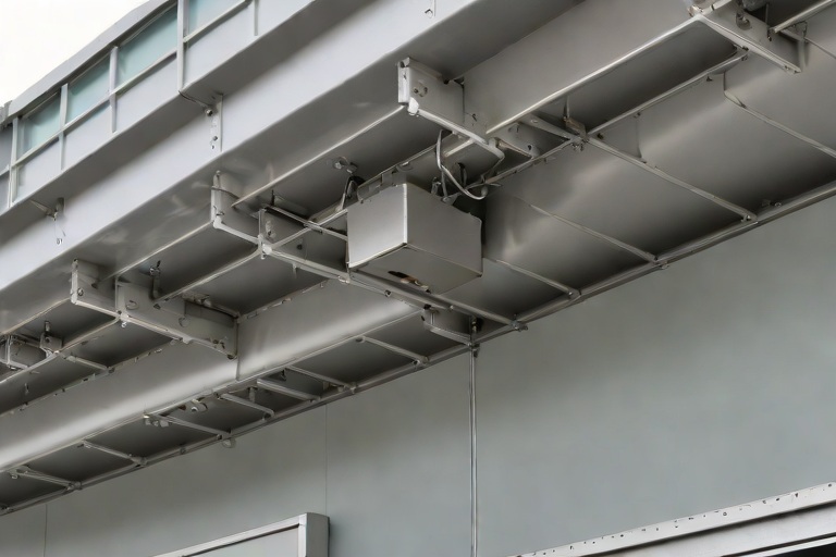
Commercial Engineering Dossier #703

Parapet Wall Heavy-Gauge 20-Gauge Kynar 500 Coping Cap Continuous Cleat Locking on Commercial Semiconductor Cleanroom Fabs

Industrial Building Envelope Sciences • Commercial Low-Slope Systems
Parapet Wall Heavy-Gauge 20-Gauge Kynar 500 Coping Cap Continuous Cleat Locking on Commercial Semiconductor Cleanroom Fabs

Wind Uplift Engineering and ANSI/SPRI ES-1 Compliance

In the high-stakes environment of a semiconductor cleanroom fab, the building envelope is not merely a shell but a critical component of the facility's contamination control system. The parapet wall represents the most vulnerable point of the building envelope, acting as a focal point for wind scour and extreme pressure differentials. To ensure structural integrity, we utilize 20-gauge heavy-gauge steel treated with a Kynar 500 finish. This thickness is a deliberate engineering choice; standard 24-gauge coping often lacks the sectional modulus required to resist the fluttering and deformation associated with high-velocity wind events common to large-scale industrial footprints.

Our engineering audit focuses on the strict adherence to ANSI/SPRI ES-1 standards, which govern the wind load resistance of metal roofing and flashing. In a semiconductor fab, the "edge zone" of the roof experiences significantly higher suction forces than the field. When wind hits the vertical face of the parapet, it creates a vortex that attempts to lift the coping cap from the substrate. By increasing the gauge to 20-gauge, we significantly increase the moment of inertia of the metal profile, reducing the likelihood of "oil-canning" or permanent deformation during a peak wind event.

  • Calculation of site-specific wind speeds based on ASCE 7-16 standards to determine required fastening frequency.
  • Application of the ES-1 wind uplift formula to ensure the coping cap can withstand pressures exceeding 60 PSF in critical corner zones.
  • Utilization of heavy-gauge steel to minimize the deflection of the metal skin, preventing the breach of the underlying waterproof membrane.
  • Verification of the substrate's compressive strength to ensure that fasteners do not pull through the masonry or steel decking under extreme suction.

Continuous Cleat Engagement and Mechanical Fastening

The traditional method of intermittent clipping is insufficient for the rigorous demands of a cleanroom facility. Intermittent fasteners create "point loads," where the stress is concentrated at a few specific intervals, leaving the gaps between fasteners susceptible to wind-driven uplift and water infiltration. To mitigate this, we implement a continuous cleat locking system. This system employs a heavy-duty galvanized steel cleat that runs the entire length of the parapet, providing a constant mechanical bond between the coping cap and the wall structure.

Continuous cleat engagement transforms the coping cap from a series of overlapping plates into a unified structural beam. This distribution of load ensures that no single fastener is bearing a disproportionate amount of the wind load. Furthermore, the continuous cleat prevents the "peeling" effect often seen at the leading edge of the coping. By locking the metal securely along its entire perimeter, we eliminate the gap where wind can enter and create a positive-pressure pocket, which is the primary cause of catastrophic coping failure in commercial roofing.

  • Elimination of "point-load" failures by distributing wind uplift forces across the entire length of the parapet.
  • Reduction of fastener fatigue by preventing the repetitive cycling of metal movement against fixed points.
  • Enhanced water shedding capabilities by ensuring the coping remains perfectly seated against the flashing.
  • Implementation of stainless steel fasteners to prevent galvanic corrosion between the Kynar 500 coated steel and the cleat system.

Thermal Expansion and Kinetic Management via Splice Plates

Material science dictates that steel expands and contracts based on ambient temperature fluctuations. In a massive semiconductor fab, the sheer length of the parapet walls means that the cumulative thermal expansion can be measured in inches. If the coping cap is fastened too rigidly, this kinetic energy will manifest as buckling, warping, or the shearing of fasteners. To manage this, we engineer custom thermal expansion splice plates that allow for controlled longitudinal movement while maintaining a watertight seal.

The splice plates are designed as overlapping sleeves with a specific tolerance that permits the 20-gauge steel to slide during thermal cycles. These plates are strategically placed at calculated intervals based on the coefficient of thermal expansion for Kynar 500 coated steel. The engineering goal is to decouple the movement of the metal from the rigidity of the building's structural frame. Without these splice plates, the internal stress would eventually compromise the perimeter peel mitigation, leading to micro-fissures in the finish and potential moisture ingress.

  • Utilization of oversized pre-drilled holes in splice plates to allow for linear thermal drift.
  • Application of high-grade silicone sealants at the splice interfaces to ensure a flexible, waterproof barrier.
  • Calculation of expansion gaps based on the maximum and minimum recorded temperatures of the geographic region.
  • Prevention of "buckling" by ensuring the metal is not "locked in" too tightly during the installation phase.

Perimeter Peel Mitigation and Envelope Integrity

The final and most critical phase of the building envelope audit is the mitigation of perimeter peel. This occurs most frequently at the corners and the termination points of the parapet. Wind currents tend to wrap around the corners of a building, creating a vacuum effect that pulls the metal away from the wall. If the termination is not properly detailed, the wind can "peel" the coping cap back, exposing the underlying insulation and membrane to the elements, which would be catastrophic for a cleanroom environment where humidity and dust control are paramount.

Our approach to peel mitigation involves a combination of heavy-duty hemmed edges and reinforced corner wraps. By folding the 20-gauge steel into a rigid, reinforced profile at the ends of the run, we create a mechanical "stop" that resists the pulling force of the wind. Additionally, we ensure that the drip edge is properly calibrated to shed water away from the face of the building, preventing hydrostatic pressure from forcing water backward under the coping cap. This comprehensive sealing strategy ensures that the building envelope remains airtight and watertight, protecting the multi-billion dollar equipment inside the fab.

  • Installation of custom-fabricated 90-degree corner wraps to eliminate open seams at the parapet turns.
  • Implementation of a continuous sealant bead at the transition between the coping and the wall flashing.
  • Verification of the drip edge projection to ensure water is cast off the building face, preventing "wall staining" and moisture seepage.
  • Final audit of all termination points using infrared thermography to detect any hidden air leaks or thermal bridges.

Aquashield Roofing Corporation

4006 Morris Ct.
Chesapeake, VA 23323
Direct Line: 757-553-5191
GPS Coordinates: 36.755164, -76.353932

Official Facebook Updates

Virginia Beach Roofing Company - Roofing Service Virginia Beach VA, Roofing Contractor

585 S Birdneck Rd #106
Virginia Beach, VA 23451
Direct Line: +17576318100
Google Maps Plus Code: RXCX+V7 Virginia Beach, Virginia
GPS Coordinates: 36.822156, -76.001565
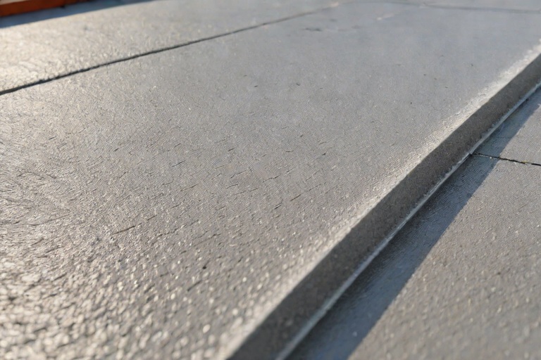
Commercial Engineering Dossier #704

Industrial Drainage Scuppers, Overflow Weirs & Heavy Downspout Expansion Bellows on Commercial Intermodal Cargo Freight Terminals

Industrial Building Envelope Sciences • Commercial Low-Slope Systems
Industrial Drainage Scuppers, Overflow Weirs & Heavy Downspout Expansion Bellows on Commercial Intermodal Cargo Freight Terminals

Hydraulic Head-Loss and Primary Scupper Integration

In the context of intermodal cargo freight terminals, the sheer scale of the roofing footprint creates a unique set of hydraulic challenges. When dealing with thousands of square feet of low-slope membrane, the primary objective is the rapid evacuation of pluvial loads to prevent hydrostatic pressure buildup. Hydraulic head-loss occurs when the resistance to flow within the drainage system exceeds the rate of precipitation, leading to an increase in the depth of water across the roof surface. For a master roofer, calculating this head-loss is not merely a theoretical exercise but a structural necessity; excess water weight can quickly exceed the dead-load capacity of the steel decking and insulation assembly.

The integration of industrial scuppers must be precision-engineered to minimize turbulence and maximize flow coefficients. We analyze the friction loss within the scupper throat and the transition to the exterior conductor. If the scupper is undersized or improperly pitched, a "bottleneck" effect occurs, increasing the head height and risking a breach of the flashing system. To mitigate this, we implement high-capacity wide-mouth scuppers that utilize a smooth interior bore to reduce the coefficient of friction, ensuring that water transitions from the roof deck to the downspout with minimal resistance.

  • Calculation of the Manning Roughness Coefficient to determine flow velocity across the membrane.
  • Assessment of the "ponding" threshold to ensure water does not remain stagnant for more than 48 hours.
  • Evaluation of scupper spacing based on the maximum allowable travel distance for water droplets.
  • Verification of flashing integrity at the penetration point to prevent capillary action and subsurface leaks.

Emergency Overflow Weir Sizing and Structural Safeguards

A critical failure in a primary drainage system—whether caused by debris accumulation from cargo handling or extreme weather events—can lead to catastrophic structural collapse if emergency overflow weirs are not correctly sized. An overflow weir acts as a fail-safe, providing a controlled path for water to exit the building envelope once the primary scuppers reach their maximum hydraulic capacity. The engineering of these weirs requires a precise understanding of the "crest length" and the "head height" over the weir, ensuring that the volume of water discharged is sufficient to keep the roof load within safe engineering limits.

From a building envelope perspective, the weir must be positioned exactly at the height where the water depth begins to threaten the structural integrity of the roof, but high enough to avoid unnecessary activation during standard rain events. We utilize the weir flow formula to determine the necessary width of the opening, ensuring that the discharge rate exceeds the peak rainfall intensity for the specific geographic region. This prevents the "damming" effect, where water piles up against the parapet wall, creating a lateral force that can compromise the masonry or steel facade of the terminal.

  • Sizing of weir openings based on the 100-year storm event data and local building codes.
  • Installation of debris screens that allow for high-volume flow while preventing large objects from clogging the weir.
  • Strategic placement of weirs to avoid discharging water directly onto pedestrian walkways or loading docks.
  • Coordination of weir height with the primary drain invert elevation to ensure sequential activation.

Conductor Head Design and Kinetic Energy Dissipation

The conductor head is the critical transition point where water moves from the horizontal plane of the roof to the vertical plane of the downspout. In massive freight terminals, the volume of water entering the conductor head can be immense, creating high-velocity turbulence and kinetic energy that can erode the roof membrane or vibrate the piping system. A poorly designed conductor head often suffers from "splashing," where water is forced back onto the roof, leading to premature degradation of the flashing and potential leaks at the roof-to-wall transition.

To combat this, we specify heavy-gauge, reinforced conductor heads with a flared geometry that slows the incoming water and directs it smoothly into the downspout. This process of kinetic energy dissipation is essential for maintaining the stability of the vertical piping. We focus on the "vortex" effect, ensuring that the head is shaped to prevent air-locking, which can restrict flow and cause the conductor to overflow. By utilizing ASTM-compliant galvanized steel or heavy-duty aluminum, we ensure that the head can withstand the abrasive force of sediment and debris common in industrial cargo environments.

  • Implementation of deep-sump conductor heads to provide a buffer for surge volumes.
  • Use of reinforced mounting brackets to prevent pipe vibration and mechanical fatigue.
  • Application of high-performance sealants and flashing to create a watertight seal between the head and the membrane.
  • Integration of debris baskets for easy maintenance and removal of industrial particulates.

Thermal Expansion Bellows and Differential Movement Joints

Intermodal terminals are subject to extreme thermal cycling, with roof temperatures fluctuating significantly between summer and winter. Because the downspouts are often long, continuous runs of metal, they are subject to linear thermal expansion and contraction. Without the inclusion of expansion bellows or slip joints, this movement manifests as bowing in the pipes, cracking in the solder joints, or, more critically, the tearing of the roof membrane where the pipe penetrates the building envelope. This is a classic failure point in commercial roofing that requires a material science approach to solve.

We integrate heavy-duty expansion bellows—flexible, reinforced joints that can compress or expand without compromising the watertight seal. These bellows are engineered to absorb the differential movement between the roof deck and the vertical piping. By calculating the coefficient of thermal expansion for the specific metal used (such as aluminum or galvanized steel), we determine the exact placement and frequency of these joints. This ensures that the piping system remains aligned and that the stress is not transferred to the flashing, which would otherwise lead to a breach in the building envelope.

  • Selection of bellows materials that are chemically compatible with the roof membrane to prevent galvanic corrosion.
  • Installation of slip-joint couplings that allow for longitudinal movement while maintaining a tight seal.
  • Verification of joint placement at intervals that match the structural expansion joints of the building.
  • Testing of bellows under extreme temperature simulations to ensure elasticity and seal integrity.

Aquashield Roofing Corporation

4006 Morris Ct.
Chesapeake, VA 23323
Direct Line: 757-553-5191
GPS Coordinates: 36.755164, -76.353932

Official Facebook Updates

Virginia Beach Roofing Company - Roofing Service Virginia Beach VA, Roofing Contractor

585 S Birdneck Rd #106
Virginia Beach, VA 23451
Direct Line: +17576318100
Google Maps Plus Code: RXCX+V7 Virginia Beach, Virginia
GPS Coordinates: 36.822156, -76.001565
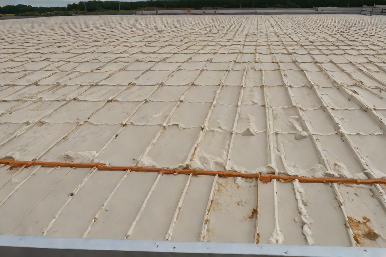
Commercial Engineering Dossier #705

AOC 581 Elastomeric Structural Mastic Detailing Around Rooftop HVAC Curbs on Commercial Port Marine Shipping Warehouses

Industrial Building Envelope Sciences • Commercial Low-Slope Systems
AOC 581 Elastomeric Structural Mastic Detailing Around Rooftop HVAC Curbs on Commercial Port Marine Shipping Warehouses

Environmental Stressors and Site Analysis in Port Marine Warehouses

The building envelope of a port marine shipping warehouse is subject to some of the most aggressive environmental conditions encountered in commercial construction. In these high-salinity environments, the interface between the rooftop membrane and mechanical equipment curbs becomes a primary point of failure. The combination of salt-laden air, extreme wind-driven rain, and constant atmospheric pressure shifts creates a corrosive environment that accelerates the degradation of standard sealants. An engineering audit of these facilities reveals that the primary cause of leakage is not typically a failure of the field membrane, but rather a breakdown in the detailing around HVAC curbs where the substrate is most prone to movement.

From a material science perspective, the high humidity and chloride levels in marine environments can lead to osmotic blistering and the chemical breakdown of low-grade polymers. When these factors are combined with the structural demands of a large-span warehouse, the building envelope must be treated as a dynamic system rather than a static shield. The objective of the audit is to ensure that the transition from the roof deck to the vertical curb flashing is completely airtight and watertight, preventing the ingress of moisture that could lead to structural steel corrosion and interior inventory loss.

  • Atmospheric salinity causing accelerated oxidation of metal flashing and curb components.
  • High-velocity wind loads creating negative pressure zones that pull at the edges of sealant beads.
  • Hydrostatic pressure buildup during heavy precipitation events, forcing water into micro-fissures.
  • UV degradation of exposed elastomeric compounds leading to premature embrittlement.

Mitigating Mechanical Vibration and Thermal Expansion Drift

One of the most overlooked aspects of rooftop detailing is the impact of mechanical vibration. HVAC units, particularly large industrial tonnage systems used in shipping warehouses, generate constant low-frequency vibrations. These oscillations are transferred directly into the curb and the surrounding roof deck. If the sealing material is too rigid, these micro-movements lead to fatigue cracking and the eventual separation of the sealant from the substrate, a phenomenon known as cohesive failure.

Furthermore, the coefficient of thermal expansion differs significantly between the metal HVAC curb and the reinforced concrete or steel deck of the warehouse. As the building undergoes diurnal thermal cycling, the curb and the roof move at different rates. This "thermal drift" creates a shearing force at the bond line. To mitigate this, the application of AOC 581 Elastomeric Structural Mastic is critical. Its high elongation properties allow the seal to stretch and contract without losing its bond, effectively acting as a shock absorber between the vibrating equipment and the static roof surface.

  • Dynamic load distribution to prevent the concentration of stress at the curb corners.
  • Utilization of high-modulus elastomeric properties to accommodate differential thermal movement.
  • Reduction of shear stress through the implementation of a flexible, wide-bead transition.
  • Prevention of "backing out" where vibration pushes the sealant away from the flashing.

Material Science and Fiber-Reinforced Trowel Application

The application of AOC 581 requires a master tradesman's approach to substrate preparation and material placement. Unlike standard caulking, this structural mastic is engineered for trowel application, allowing for a thicker, more robust build-up that can bridge larger gaps and provide a superior waterproof barrier. The integration of fiber reinforcement within the mastic is a critical engineering feature; these fibers provide internal structural scaffolding, preventing the material from sagging during the curing process and increasing its puncture resistance once set.

The trowel application process ensures a mechanical bond that is far superior to extruded beads. By forcing the mastic into the pores of the substrate and overlapping the flashing with a consistent, tapered edge, the installer creates a seamless transition. This eliminates the "lip" that often catches wind-blown debris and prevents the formation of water-pooling pockets. The fiber-reinforced matrix ensures that even if the building experiences a significant seismic or structural shift, the mastic maintains its integrity, bridging the gap without tearing.

  • Fiber-reinforcement to increase tensile strength and prevent shrinkage during the curing phase.
  • Trowel-applied thickness to ensure a deep-seated seal that resists hydrostatic pressure.
  • Enhanced adhesion properties that bond to both galvanized steel and modified bitumen membranes.
  • Tapered edge detailing to promote efficient water shedding away from the curb base.

Engineering Audit and Quality Assurance Protocols

A comprehensive building envelope audit concludes with a rigorous verification process to ensure the AOC 581 installation meets ASTM and ANSI standards for commercial roofing. The audit focuses on the "critical transition zones"—the areas where the horizontal roof plane meets the vertical curb. Using infrared thermography, engineers can detect subsurface moisture or voids in the mastic application that are invisible to the naked eye. This non-destructive testing ensures that the seal is monolithic and free of pinholes or air pockets that could lead to future leaks.

The final stage of quality assurance involves a simulated flood test or a rain-simulation test to verify the watertightness of the curb detailing. The goal is to ensure that the elastomeric seal remains intact even under conditions of extreme water volume. By documenting the performance of the AOC 581 system against the baseline of previous failures, the audit provides a technical roadmap for the long-term maintenance of the facility. The result is a building envelope that is not only watertight but is engineered to withstand the brutal realities of a port marine environment.

  • Verification of bond strength through non-destructive pull tests on sample areas.
  • Infrared scanning to identify thermal bridges or moisture entrapment behind the curbing.
  • Adherence to ASTM E2128 standards for the evaluation of roof leakages.
  • Long-term durability projections based on the elastomeric recovery rate of the mastic.

Aquashield Roofing Corporation

4006 Morris Ct.
Chesapeake, VA 23323
Direct Line: 757-553-5191
GPS Coordinates: 36.755164, -76.353932

Official Facebook Updates

Virginia Beach Roofing Company - Roofing Service Virginia Beach VA, Roofing Contractor

585 S Birdneck Rd #106
Virginia Beach, VA 23451
Direct Line: +17576318100
Google Maps Plus Code: RXCX+V7 Virginia Beach, Virginia
GPS Coordinates: 36.822156, -76.001565
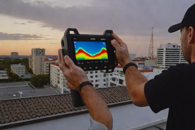
Commercial Engineering Dossier #706

UL 2218 Class 4 Severe Hail Defense on Commercial Municipal Sports & Convention Arenas

Industrial Building Envelope Sciences • Commercial Low-Slope Systems
UL 2218 Class 4 Severe Hail Defense on Commercial Municipal Sports & Convention Arenas

The Engineering Challenge of Large-Span Municipal Envelopes

When auditing a municipal sports and convention arena, the scale of the roof introduces a set of variables that standard commercial projects simply do not encounter. These structures typically feature massive, uninterrupted spans of roofing membrane, often stretching across several hundred thousand square feet. From a building envelope perspective, this creates a vast target for atmospheric hazards. In the context of severe weather, the primary concern is not merely the wind uplift, but the concentrated kinetic energy delivered by large-diameter hail. A failure in a single square foot of a convention center roof can lead to catastrophic interior water damage, compromising millions of dollars in electronic equipment, flooring, and athletic surfaces.

The vulnerability of these arenas is compounded by the geometry of the roof. Many municipal arenas utilize low-slope designs that allow hail to accumulate and slide, potentially creating a "scouring" effect that wears down the protective granules or the polymer surface of the membrane. As a master roofer, my focus during an engineering audit is to evaluate the entire assembly—from the structural deck up to the weather-exposed surface—to ensure the system functions as a cohesive unit rather than a collection of independent layers.

  • Evaluation of roof geometry to identify high-impact zones and water collection points.
  • Analysis of the structural deck's ability to support the dead load of high-performance insulation.
  • Assessment of flashing and perimeter detailing where hail-driven rain often infiltrates.
  • Review of existing drainage capacity to prevent hydrostatic pressure buildup during storm events.

Analyzing UL 2218 Class 4 Performance and Kinetic Energy

To achieve a truly resilient envelope, we specify UL 2218 Class 4 standards. For the uninitiated, UL 2218 is the gold standard for hail impact resistance. While lower classes may withstand small stones, Class 4 is engineered to resist the impact of larger, more destructive hail stones without fracturing or puncturing. The physics of this defense relies on kinetic energy attenuation. When a hail stone strikes a roof, it delivers a massive amount of energy in a fraction of a second. If the roofing system is too rigid, the energy results in a crack; if it is too soft, it results in a puncture.

A Class 4 rated system is designed to dissipate this energy across a wider surface area. This is achieved through a combination of high-tensile strength membranes and a supportive substrate that allows for a minute amount of deflection without permanent deformation. By absorbing the shock and distributing the load, the system prevents the "punch-through" effect that typically leads to immediate leaks. In a municipal arena setting, where the cost of a roof replacement is astronomical, this level of attenuation is non-negotiable.

  • Kinetic energy dissipation through advanced polymer blends in the membrane.
  • Reduction of surface tension to prevent the "shattering" effect of ice impact.
  • Utilization of reinforced scrims to maintain structural integrity under extreme pressure.
  • Validation of impact resistance through standardized steel ball drop testing.

Compressive Strength and the 25 PSI Threshold

One of the most overlooked aspects of hail defense is the role of the insulation core. Many contractors focus solely on the membrane, but the membrane is only as strong as the support beneath it. If the insulation—typically polyisocyanurate or a similar closed-cell foam—collapses under the impact of a hail stone, the membrane will stretch and eventually tear, even if the hail stone never actually punctures the surface. This is known as a compressive failure. To prevent this, we mandate a compressive strength exceeding 25 PSI (pounds per square inch) for the insulation core.

When a hail stone strikes a roof with a low-density core, the insulation "craters." This cratering creates a localized depression that becomes a point of weakness. Over time, these depressions collect water and debris, leading to premature membrane degradation and potential leaks. By utilizing high-density cores that exceed 25 PSI, we ensure that the substrate remains rigid enough to support the membrane during a high-velocity impact. This maintains the building envelope's geometry and ensures that the load is transferred efficiently to the structural deck.

  • Prevention of "dimpling" or cratering in the insulation layer during severe storms.
  • Maintenance of the thermal bridge to ensure energy efficiency is not compromised by crushed cells.
  • Enhanced support for maintenance traffic and HVAC equipment on the roof surface.
  • Long-term stability of the roof plane to ensure positive drainage toward scuppers.

Audit Methodology and Long-Term Envelope Integrity

A comprehensive engineering audit for a municipal arena goes beyond a simple visual walk-through. We employ a rigorous methodology to ensure the envelope is performing to specification. This begins with infrared thermography to detect hidden moisture trapped within the insulation, which can soften the core and reduce its compressive strength. We then move to destructive testing in select areas, taking core samples to verify that the installed materials match the specified UL 2218 Class 4 requirements and that the insulation density meets the 25 PSI threshold.

The final phase of the audit focuses on the "weak links"—the penetrations. No matter how strong the main field of the roof is, the system is only as good as its seams and flashings. We examine the transition points where the roof meets the parapet walls and the mechanical curbs. In a severe hail event, wind-driven rain is pushed into these joints with immense force. If the seal is compromised, the hail defense is irrelevant. Our goal is to create a monolithic shield that protects the interior of the arena regardless of the severity of the storm.

  • Implementation of infrared scanning to identify subsurface anomalies and moisture pockets.
  • Core sampling to verify material density and adherence to ASTM standards.
  • Detailed inspection of all TPO, PVC, or EPDM seams using high-intensity lighting.
  • Verification of fastener patterns to ensure the system can withstand simultaneous hail and wind uplift.

Aquashield Roofing Corporation

4006 Morris Ct.
Chesapeake, VA 23323
Direct Line: 757-553-5191
GPS Coordinates: 36.755164, -76.353932

Official Facebook Updates

Virginia Beach Roofing Company - Roofing Service Virginia Beach VA, Roofing Contractor

585 S Birdneck Rd #106
Virginia Beach, VA 23451
Direct Line: +17576318100
Google Maps Plus Code: RXCX+V7 Virginia Beach, Virginia
GPS Coordinates: 36.822156, -76.001565
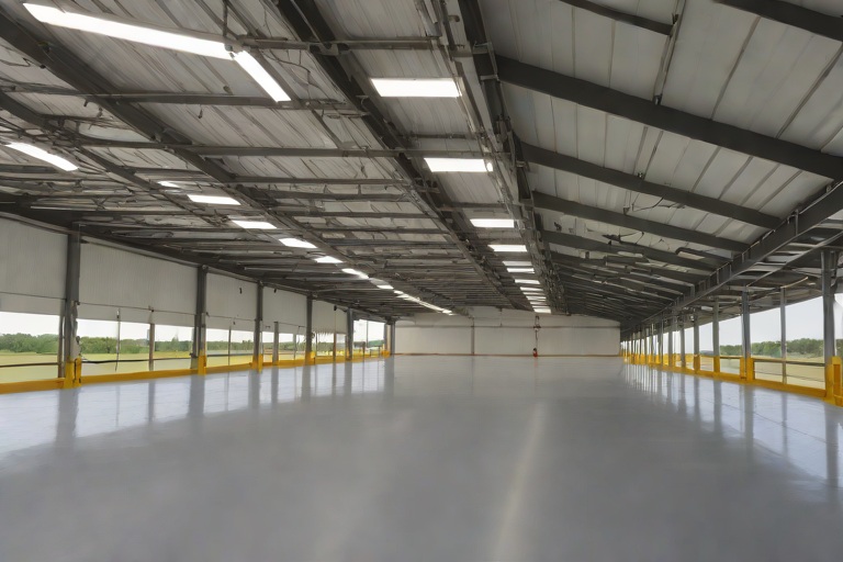
Commercial Engineering Dossier #707

Non-Destructive Substrate Moisture Scans on Commercial Multi-Family Urban Residential Towers

Industrial Building Envelope Sciences • Commercial Low-Slope Systems
Non-Destructive Substrate Moisture Scans on Commercial Multi-Family Urban Residential Towers

The Engineering Challenge of Urban High-Rise Envelopes

In the context of multi-family urban residential towers, the building envelope is not merely a cover but a complex engineered system designed to manage extreme thermal gradients and hydrostatic pressure. When these systems fail, the resulting moisture intrusion often remains undetected until it reaches a critical mass, manifesting as interior ceiling stains or structural degradation. The primary challenge in these high-density environments is the sheer scale of the roof assembly, which typically consists of multiple layers of insulation—often polyisocyanurate (polyiso)—and a reinforced waterproofing membrane. Because these materials are designed to be watertight, they frequently trap moisture beneath the surface, creating a hidden reservoir that accelerates the decay of the roof deck and supporting steel.

A traditional "tear-off" approach to leak detection is fiscally irresponsible and operationally disruptive in an occupied residential tower. Instead, a master-level engineering audit focuses on the science of the building envelope to identify the precise boundaries of subsurface saturation. By treating the roof as a singular, integrated system, we can analyze how wind-driven rain, flashing failures, and thermal bridging contribute to moisture accumulation. The goal is to transition from reactive patching to a proactive, data-driven remediation strategy that preserves the structural integrity of the tower while minimizing tenant disturbance.

  • Analysis of thermal bridging at parapet walls and mechanical penthouse interfaces.
  • Evaluation of membrane elasticity and fatigue in high-UV urban environments.
  • Assessment of drainage efficiency and the impact of ponding water on substrate saturation.
  • Identification of capillary action pathways where moisture migrates horizontally through insulation layers.

Non-Destructive Moisture Detection (NDMO) Methodology

To accurately map the "wet footprint" of a failing roof system, we employ Non-Destructive Moisture Detection (NDMO). This process begins with an Infrared (IR) thermographic scan, which identifies thermal anomalies across the roof surface. Because wet insulation has a higher thermal mass than dry insulation, it retains heat differently during the cooling cycle of the evening. By capturing these temperature differentials, we can visualize the subsurface saturation boundaries that are invisible to the naked eye. This provides a macro-level map of the moisture distribution, allowing us to pinpoint the exact areas requiring deeper investigation.

Following the IR scan, we utilize electronic moisture meters that employ dielectric constant analysis. These devices send a low-frequency signal through the membrane into the substrate; the return signal varies based on the moisture content of the insulation. This allows us to establish a precise grid of moisture readings, transforming a vague "wet area" into a quantified saturation map. This rigorous mapping prevents the common industry error of over-estimating or under-estimating the scope of work, ensuring that every square inch of saturated material is identified without unnecessary demolition of dry components.

  • Utilization of high-resolution FLIR thermography to detect latent heat signatures.
  • Implementation of a grid-based moisture mapping system for spatial accuracy.
  • Calibration of sensors to account for the specific dielectric properties of polyiso and EPS insulation.
  • Correlation of thermal anomalies with known architectural vulnerabilities, such as HVAC curb flashing.

Validating Data through Core Analysis and Thresholds

While NDMO provides a comprehensive map, it remains a proxy measurement. To achieve engineering-grade certainty, we must validate these findings through destructive core sampling. This process involves extracting small, cylindrical sections of the entire roof assembly—from the membrane down to the structural deck. These cores are then analyzed in a controlled environment to determine the actual moisture content by weight. By comparing the physical moisture percentage of the core sample to the electronic readings from the NDMO scan, we establish a "ground truth" for the specific building envelope.

In commercial roofing engineering, we typically look for a moisture threshold of 30% for polyisocyanurate insulation. Once the moisture content exceeds this threshold, the insulation's R-value is significantly compromised, and the risk of mold growth and deck corrosion increases exponentially. This validation phase is critical because it allows us to differentiate between "nuisance moisture"—small amounts of condensation—and "systemic saturation," which indicates a breach in the primary waterproofing layer. This scientific approach ensures that the remediation is based on material science rather than visual guesswork.

  • Extraction of full-depth cores using precision drilling equipment to avoid substrate contamination.
  • Calculation of moisture content using the oven-dry method for maximum accuracy.
  • Cross-referencing core data with ASTM standards for insulation performance.
  • Establishing a saturation baseline to determine the "cutoff line" for insulation removal.

Surgical Excision and Remediation Strategy

The final phase of the audit is the execution of surgical wet insulation excision. Rather than a blanket replacement of the roof, which is costly and wasteful, we use the validated saturation maps to perform targeted removals. This "surgical" approach involves cutting out only the sections of insulation that have exceeded the 30% moisture threshold. By removing the saturated material, we eliminate the source of potential deck corrosion and prevent the "wicking" effect, where moisture travels from wet areas into previously dry sections of the roof.

Once the wet insulation is excised, the structural deck is inspected for oxidation or pitting. If the deck is sound, new high-density insulation is installed and meticulously seamed to prevent future infiltration. The final membrane tie-in is performed using high-temperature welding or reinforced adhesives, ensuring a seamless transition between the new and existing envelope. This method not only reduces material waste and labor costs but also ensures that the building envelope is restored to its original engineering specifications without compromising the overall structural load of the tower.

  • Precision cutting of saturated insulation based on the validated moisture grid.
  • Mechanical cleaning and priming of the structural deck to ensure a clean bonding surface.
  • Installation of tapered insulation systems to improve drainage and eliminate future ponding.
  • Rigorous water testing and electronic leak detection (ELD) to verify the integrity of the new seal.

Aquashield Roofing Corporation

4006 Morris Ct.
Chesapeake, VA 23323
Direct Line: 757-553-5191
GPS Coordinates: 36.755164, -76.353932

Official Facebook Updates

Virginia Beach Roofing Company - Roofing Service Virginia Beach VA, Roofing Contractor

585 S Birdneck Rd #106
Virginia Beach, VA 23451
Direct Line: +17576318100
Google Maps Plus Code: RXCX+V7 Virginia Beach, Virginia
GPS Coordinates: 36.822156, -76.001565
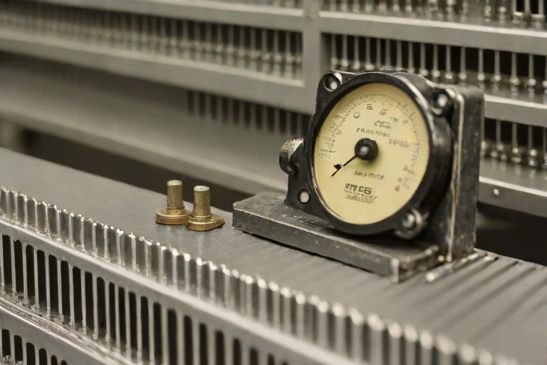
Commercial Engineering Dossier #708

Sub-Zero Cold Storage Downward Vapor Drive & Self-Adhered SBS Barriers on Commercial Public Transit Maintenance Bus Barns

Industrial Building Envelope Sciences • Commercial Low-Slope Systems
Sub-Zero Cold Storage Downward Vapor Drive & Self-Adhered SBS Barriers on Commercial Public Transit Maintenance Bus Barns

The Mechanics of Downward Vapor Drive in Transit Facilities

In the specialized environment of a Public Transit Maintenance Bus Barn, the building envelope is subjected to extreme hygrothermal stress. Unlike standard commercial warehouses, these facilities often feature massive open bays, high-volume vehicle movement, and localized sub-zero cold storage areas for specialized parts or chemical storage. When these facilities are engineered with an inverted thermal envelope, we encounter a phenomenon known as downward vapor drive. This occurs when the interior environment is maintained at a significantly lower temperature than the interstitial spaces within the roof assembly, effectively reversing the traditional direction of moisture migration.

From an engineering perspective, vapor moves from areas of high partial pressure to low partial pressure. In a sub-zero or heavily cooled transit facility, the interior air holds very little moisture, but the exterior ambient air—especially during humid shoulder seasons—is saturated. This creates a pressure gradient that forces water vapor to migrate downward through the roofing membrane and insulation toward the conditioned interior. If the assembly is not designed to manage this specific drive, the moisture will accumulate at the first cold surface it encounters, leading to catastrophic failure of the substrate and structural steel.

  • Atmospheric pressure differentials that force humid exterior air into the roof plenum.
  • The "stack effect" exacerbated by large bay doors, which pulls moisture upward and then pushes it laterally across the roof deck.
  • Thermal bridging at parapet walls and curb details that accelerate localized cooling.
  • The risk of interstitial condensation when vapor reaches its saturation point within the insulation layers.

Dew Point Migration and Interstitial Condensation Control

The primary objective of a building envelope audit for a bus barn is the identification of the dew point—the exact temperature at which air becomes saturated and water vapor condenses into liquid. In an inverted thermal system, the dew point often shifts to the underside of the roof deck. If a vapor retarder is incorrectly placed on the exterior side of the insulation, it traps moisture within the polyisocyanurate (polyiso) layers. This leads to "wet-out," where the insulation loses its R-value and the steel deck begins to oxidize, compromising the structural integrity of the facility.

To mitigate this, we implement a rigorous dew point migration control strategy. This involves calculating the specific vapor permeability of every material in the stack. By utilizing a high-performance, low-permeance barrier on the "warm" side of the assembly (which, in a downward drive scenario, is the exterior), we prevent the humid outside air from ever entering the thermal mass. This ensures that the interior environment remains dry and the structural steel remains protected from the corrosive effects of condensed water droplets.

  • Calculation of the vapor drive using the ASHRAE fundamentals for climate-specific humidity.
  • Analysis of the "Critical Surface" where the temperature drops below the dew point.
  • Implementation of a continuous air barrier to eliminate convective heat loss.
  • Monitoring of moisture content in the substrate using infrared thermography to detect hidden saturation.

Engineering the Seal: Self-Adhered SBS Barriers

For the transit barn application, we specify self-adhered SBS (Styrene-Butadiene-Styrene) modified bitumen membranes. The choice of SBS over traditional APP or TPO is based on the need for superior elasticity and a monolithic bond to the substrate. In a facility with constant vibrations from heavy diesel engines and the thermal expansion and contraction of a massive steel roof, a mechanically fastened system is prone to fastener back-out and puncture. Self-adhered SBS provides a full-surface bond, which eliminates the air gap between the membrane and the insulation, effectively killing the "wind-wash" effect that often strips heat from the roof deck.

The self-adhered nature of these barriers is critical for vapor control. Because the membrane adheres to every contour of the roof, it creates an airtight seal that prevents the aforementioned downward vapor drive from finding a path of least resistance. This "cold-applied" approach also removes the risks associated with open-flame torching in a facility that may house flammable cleaning solvents or fuel additives. The result is a seamless, rubberized skin that acts as both the primary waterproofing layer and the primary vapor barrier.

  • High elongation properties that accommodate the structural movement of long-span steel trusses.
  • Elimination of thermal bridging typically caused by mechanical fasteners.
  • Superior puncture resistance against maintenance traffic and HVAC equipment vibrations.
  • Enhanced chemical resistance to the exhaust pollutants common in bus maintenance bays.

Thermal Bridging and Staggered Multi-Layer Polyiso Installation

To achieve the required R-value while minimizing the risk of thermal bridging, the installation of polyisocyanurate (polyiso) insulation must be executed with surgical precision. A common failure in commercial roofing is the use of a single, thick layer of insulation. This creates "seam-leakage," where vapor and heat bypass the insulation through the gaps between the boards. To counter this, we employ a staggered multi-layer approach, utilizing two or more layers of polyiso with offset joints.

By staggering the joints, we ensure that no single vertical seam runs from the roof surface down to the steel deck. This forces the vapor to take a tortuous path, significantly increasing the effective resistance of the assembly. Furthermore, we specify a high-density polyiso with a closed-cell structure to ensure that the material does not act as a sponge for any moisture that might penetrate the primary SBS barrier. This engineering approach ensures a consistent thermal blanket across the entire footprint of the bus barn, preventing the localized cold spots that lead to condensation.

  • Offsetting seams by at least 12 inches between layers to break the vertical vapor path.
  • Application of a joint sealant or flashing tape to critical transitions and perimeter edges.
  • Utilization of high-density

Aquashield Roofing Corporation

4006 Morris Ct.
Chesapeake, VA 23323
Direct Line: 757-553-5191
GPS Coordinates: 36.755164, -76.353932

Official Facebook Updates

Virginia Beach Roofing Company - Roofing Service Virginia Beach VA, Roofing Contractor

585 S Birdneck Rd #106
Virginia Beach, VA 23451
Direct Line: +17576318100
Google Maps Plus Code: RXCX+V7 Virginia Beach, Virginia
GPS Coordinates: 36.822156, -76.001565
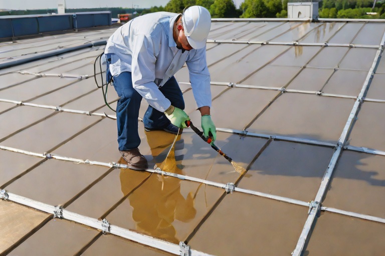
Commercial Engineering Dossier #709

Structural Deck Fastener Pull-Out Testing on 22-Gauge Corrugated Steel Decks on Commercial Government Secure Records Archives

Industrial Building Envelope Sciences • Commercial Low-Slope Systems
Structural Deck Fastener Pull-Out Testing on 22-Gauge Corrugated Steel Decks on Commercial Government Secure Records Archives

Substrate Analysis and Baseline Envelope Audit

In the high-stakes environment of a Government Secure Records Archive, the building envelope is not merely a weather barrier but a critical component of the facility's security and structural integrity. The subject facility utilizes a 22-gauge corrugated steel deck, a heavy-duty substrate chosen for its superior load-bearing capacity to support high-density mobile shelving and archival storage. However, the structural performance of the roofing system is entirely dependent on the efficacy of the fastener interface between the deck and the membrane attachment points. A comprehensive engineering audit was initiated to determine if the existing fastener patterns met the current building code requirements for wind uplift and structural stability.

The initial phase of the audit involved a meticulous visual inspection of the deck profile and the assessment of the steel's gauge consistency. While 22-gauge steel provides significant rigidity, it presents specific challenges regarding fastener penetration and thread engagement. The corrugated nature of the deck creates varying thickness points, which can lead to inconsistent pull-out resistance if fasteners are not precisely positioned in the ribs or the flats as specified by the original engineering drawings. Our team focused on identifying signs of substrate fatigue, including localized deformation and oxidation at the fastener entry points.

  • Verification of steel gauge using ultrasonic thickness gauges to confirm 22-gauge consistency.
  • Mapping of fastener density across the roof perimeter versus the field areas.
  • Inspection for "oil-canning" or buckling in the corrugated flutes that could compromise fastener seating.
  • Assessment of the existing moisture barrier to ensure no interstitial condensation has accelerated deck corrosion.

Calibrated Mechanical Pull Testing Methodology

To quantify the actual withdrawal resistance of the fasteners, we employed calibrated mechanical pull testing. This process involves the use of a digital force gauge and a specialized pull-tester that applies a controlled, linear axial load to the fastener head. Unlike a simple "tug test," calibrated pull testing provides a precise measurement of the force required to cause a fastener failure or a substrate pull-through. For a government archive, the margin for error is zero; therefore, we established a minimum withdrawal resistance threshold based on the calculated dead load of the roof and the anticipated wind-uplift pressures.

The testing protocol required the removal of the roofing membrane at strategic intervals to expose the fastener heads. Each test was conducted until the fastener reached its ultimate failure point or met the predetermined safety threshold. We observed that the 22-gauge steel provided a robust grip, but the failure mode often shifted from the fastener itself to the surrounding steel if the fastener was improperly torqued. The data collected allowed us to create a statistical bell curve of the fastener performance across the entire roof surface, identifying "weak zones" where the deck may have been compromised by previous leaks or improper installation.

  • Utilization of ASTM-compliant digital force gauges calibrated to within 0.1% accuracy.
  • Application of incremental loading to determine the elastic and plastic deformation limits of the fastener.
  • Comparison of field-tested results against the manufacturer's theoretical withdrawal values.
  • Documentation of failure modes: thread stripping, head shear, or substrate pull-through.

Fastener Corrosion Diagnostics and Material Science

A critical component of the building envelope audit was the diagnostic analysis of fastener corrosion. In a secure archive, the interior environment is strictly controlled, but the exterior envelope is subject to atmospheric pollutants and thermal cycling. We examined the fasteners for signs of galvanic corrosion, which occurs when dissimilar metals—such as the zinc coating of the fastener and the steel of the deck—interact in the presence of an electrolyte. Because 22-gauge steel is thicker, it can sometimes trap moisture in the corrugation laps, creating a micro-environment conducive to pitting corrosion.

Our analysis revealed that several fasteners had suffered from "sacrificial coating depletion," where the protective zinc layer had been completely consumed, leaving the base steel vulnerable to oxidation. This corrosion reduces the effective diameter of the fastener shaft, thereby decreasing the shear strength and the overall withdrawal resistance. We employed high-resolution borescope inspections to examine the fastener shank's engagement within the steel deck, ensuring that the threads had not been compromised by hidden oxidation layers. This material science approach ensures that the fasteners are not just holding today, but will maintain their structural integrity for the remainder of the building's lifecycle.

  • Analysis of zinc-carbon coatings to determine the rate of sacrificial anode depletion.
  • Identification of crevice corrosion occurring at the interface of the fastener head and the corrugated rib.
  • Evaluation of the chemical compatibility between the fastener alloy and the 22-gauge steel substrate.
  • Testing for the presence of chlorides or sulfates that may have penetrated the membrane and accelerated corrosion.

Wind-Zone Schedules and Engineering Validation

The final stage of the case study involved reconciling the pull-test data with the regional wind-zone schedules. Using ASCE 7 standards, we calculated the peak pressure coefficients for the archive's roof, specifically focusing on the corners and perimeter edges where wind suction is most severe. The "wind-zone schedule" dictates the required fastener spacing to prevent the membrane from peeling away from the deck during a high-wind event. By comparing the actual withdrawal resistance found during our mechanical testing to the required uplift resistance, we were able to validate the safety factor of the entire system.

The results indicated that while the field areas of the roof were well within the safety margins, the perimeter zones required an increase in fastener density. The 22-gauge deck provided an excellent foundation, but the wind-load calculations demanded a more aggressive fastening pattern to counteract the localized pressure spikes. We provided the facility managers with a revised fastening schedule, specifying the exact coordinates for additional reinforcements. This engineering validation ensures that the Government Secure Records Archive remains a fortress, protecting irreplaceable data from both structural failure and environmental infiltration.

  • Calculation of maximum uplift pressures based on building height and local wind-speed categories.
  • Development of a revised fastener map to optimize load distribution across the 22-gauge deck.
  • Verification of the "Safety Factor" (SF), ensuring a minimum 1.5x multiplier over the maximum predicted load.
  • Final certification of the building envelope's structural readiness for extreme weather events.

Aquashield Roofing Corporation

4006 Morris Ct.
Chesapeake, VA 23323
Direct Line: 757-553-5191
GPS Coordinates: 36.755164, -76.353932

Official Facebook Updates

Virginia Beach Roofing Company - Roofing Service Virginia Beach VA, Roofing Contractor

585 S Birdneck Rd #106
Virginia Beach, VA 23451
Direct Line: +17576318100
Google Maps Plus Code: RXCX+V7 Virginia Beach, Virginia
GPS Coordinates: 36.822156, -76.001565
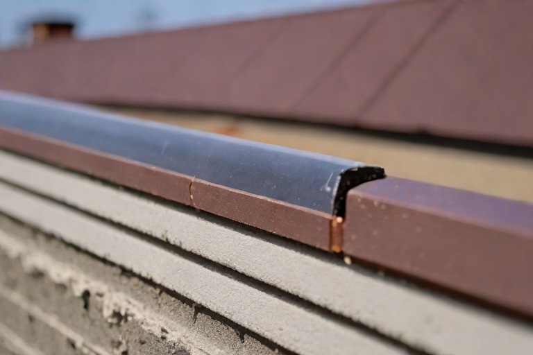
Commercial Engineering Dossier #710

Electronic Vector Mapping (EVM) Low-Voltage Membrane Breach Detection on Commercial Pharmaceutical Production Facilitys

Industrial Building Envelope Sciences • Commercial Low-Slope Systems
Electronic Vector Mapping (EVM) Low-Voltage Membrane Breach Detection on Commercial Pharmaceutical Production Facilitys

The Criticality of the Pharmaceutical Building Envelope

In the realm of commercial pharmaceutical production, the building envelope is not merely a shelter; it is a primary component of the facility's sterile containment strategy. When managing a high-stakes production environment, the roof assembly serves as the first line of defense against atmospheric contaminants and moisture ingress. A single breach in the membrane, even one invisible to the naked eye, can introduce humidity fluctuations or mold spores that jeopardize millions of dollars in pharmaceutical batches and violate stringent FDA and ISO cleanroom standards.

Traditional roofing audits often rely on visual inspections or infrared thermography, both of which are reactive rather than proactive. Thermography requires a significant temperature differential to be effective and often fails to detect microscopic pinholes until the insulation is already saturated. For a pharmaceutical facility, waiting for a visible leak is an unacceptable risk. We approach the envelope as a precision-engineered system, where the goal is absolute impermeability and verifiable integrity across thousands of square feet of TPO or PVC membrane.

  • Compliance with ASTM E2127 for standard practice for installing roof antenna mounts and penetrations.
  • Mitigation of interstitial condensation within the insulation layers.
  • Prevention of airborne particulate infiltration through membrane micro-fractures.
  • Adherence to ANSI standards for commercial roofing material durability and installation.

Engineering the Conductive Underlayment Vector Grid

To move beyond the limitations of visual inspection, we implement Electronic Vector Mapping (EVM). This system utilizes a specialized conductive underlayment installed beneath the primary waterproofing membrane. This underlayment acts as a continuous, low-voltage electrical grid. By applying a controlled, low-voltage current across the surface, we establish a baseline electrical resistance across the entire roof plane. Any breach in the overlying membrane—whether it be a puncture from a technician's tool or a failure in a heat-welded seam—alters the electrical field at that specific coordinate.

The "vector" component of this technology allows us to triangulate the exact location of a breach by measuring the voltage drop and current flow across the grid. Unlike traditional electronic leak detection (ELD), which often requires the roof to be flooded with water to create a conductive path, EVM can operate in a dry state or identify the exact moment moisture begins to penetrate the membrane. This transforms the roof into a giant sensor, providing real-time data on the state of the envelope's integrity.

  • Installation of a conductive copper or carbon-infused mesh beneath the primary membrane.
  • Calibration of low-voltage power supplies to prevent interference with facility electronics.
  • Establishment of a reference baseline to account for natural material variance.
  • Integration of vector nodes for precise X-Y coordinate mapping of the roof surface.

Precision Diagnostics and Microscopic Pinhole Identification

The true value of EVM is realized during the pinpointing of microscopic pinholes. In a pharmaceutical setting, a puncture as small as 0.1mm can be catastrophic. These "micro-breaches" are often caused by improper fastening of flashing or mechanical vibrations from heavy HVAC equipment on the roof. Using a high-sensitivity vector receiver, our engineers scan the membrane. When the receiver passes over a breach, the disruption in the electrical field triggers an immediate signal, allowing us to mark the exact spot for repair.

This process eliminates the "search and destroy" method of roofing repair, where contractors cut large holes in the membrane hoping to find the leak. Instead, we employ a surgical approach. Once the vector map identifies the breach, we perform a localized verification and apply a precision heat-weld patch. This ensures that the membrane's structural integrity is maintained and that the repair does not introduce new vulnerabilities into the system. The material science behind this involves understanding the dielectric properties of the membrane and how they interact with the conductive grid below.

  • Detection of "invisible" punctures that bypass standard flood testing.
  • Elimination of unnecessary membrane demolition during the repair process.
  • Rapid identification of seam failures in high-stress areas near parapets and drains.
  • Verification of weld quality across 100% of the membrane surface area.

Non-Destructive Quality Certification and Lifecycle Assurance

The final phase of the Aquashield engineering audit is the issuance of a Non-Destructive Quality Certification. Because EVM does not require the physical destruction of the roof to verify its performance, we can certify the entire envelope without compromising its lifespan. This certification provides the pharmaceutical facility's stakeholders with empirical evidence that the building envelope is hermetically sealed. This is a critical requirement for facilities pursuing LEED certification or those operating under strict regulatory oversight where documentation of "due diligence" is mandatory.

Beyond the initial installation, the EVM system provides a permanent diagnostic infrastructure. During annual audits, we can re-scan the vector grid to identify new breaches caused by weathering or foot traffic. This shifts the maintenance paradigm from "repair upon failure" to "predictive maintenance." By treating the roof as a piece of engineered equipment rather than a passive cover, we extend the lifecycle of the asset and ensure the uninterrupted operation of the production facility below.

  • Provision of a comprehensive digital map detailing all verified seal points.
  • Reduction in long-term operational costs by preventing interior water damage.
  • Establishment of a baseline for annual non-destructive testing (NDT) protocols.
  • Guaranteed adherence to the highest standards of commercial building envelope engineering.

Aquashield Roofing Corporation

4006 Morris Ct.
Chesapeake, VA 23323
Direct Line: 757-553-5191
GPS Coordinates: 36.755164, -76.353932

Official Facebook Updates

Virginia Beach Roofing Company - Roofing Service Virginia Beach VA, Roofing Contractor

585 S Birdneck Rd #106
Virginia Beach, VA 23451
Direct Line: +17576318100
Google Maps Plus Code: RXCX+V7 Virginia Beach, Virginia
GPS Coordinates: 36.822156, -76.001565
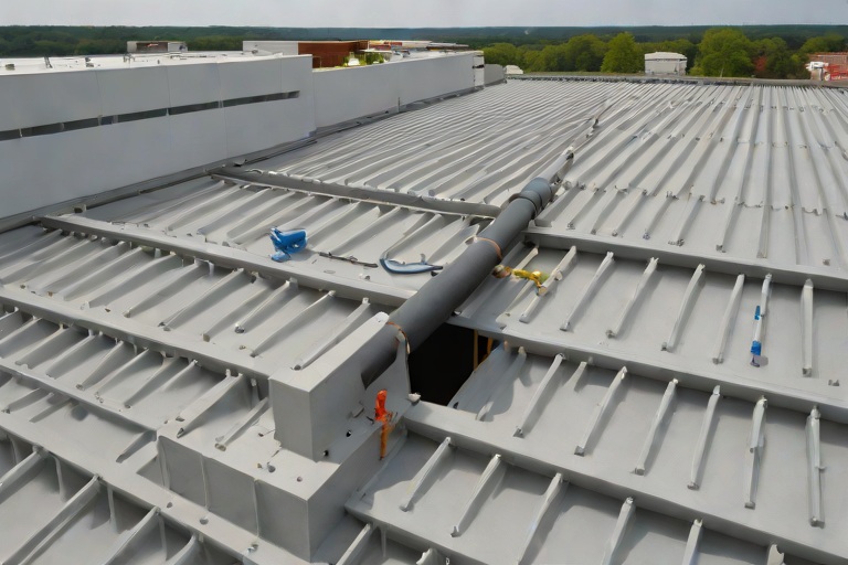
Commercial Engineering Dossier #711

Liquid-Applied PMMA & Polyurethane Fleece-Reinforced Flashing Resins on Commercial Historic Sanctuary & Education Annexs

Industrial Building Envelope Sciences • Commercial Low-Slope Systems
Liquid-Applied PMMA & Polyurethane Fleece-Reinforced Flashing Resins on Commercial Historic Sanctuary & Education Annexs

Envelope Audit and Substrate Analysis of Historic Structures

The engineering audit of the Historic Sanctuary and Education Annex revealed a complex failure pattern typical of aging commercial envelopes. The primary challenge lay in the differential movement between the original masonry of the sanctuary and the expanded structural frame of the education annex. Over decades, the interface between these two distinct building masses had developed significant stress fractures, leading to systemic water infiltration. The substrate consisted of a mixture of degraded built-up roofing (BUR) and porous historic brickwork, which had become saturated due to failed flashing at the parapet walls.

From a building envelope perspective, the priority was to eliminate hydrostatic pressure buildup within the wall assemblies. The audit identified that traditional sheet-membrane systems would be insufficient due to the irregular geometry of the historic cornices and the presence of numerous structural penetrations. The goal was to establish a monolithic, seamless waterproof barrier that could accommodate the high coefficient of thermal expansion associated with the building's large surface area and varying material densities.

  • Identification of thermal bridging at the junction of the sanctuary and annex.
  • Analysis of substrate moisture content to prevent osmotic blistering during resin application.
  • Mapping of structural movement joints to ensure the new membrane could bridge dynamic gaps.
  • Evaluation of existing I-beam stanchions for corrosion and surface preparation requirements.

Chemical Kinetics of Cold-Applied PMMA Resins

To address the demands of a high-traffic education facility and a historic sanctuary, we specified a Polymethyl Methacrylate (PMMA) cold-applied resin system. Unlike traditional bitumen or polyurethane coatings, PMMA is a thermosetting plastic that cures via a rapid chemical reaction rather than solvent evaporation. This rapid cure kinetics is critical in commercial environments where downtime is not an option; the resin reaches full structural strength within hours, allowing the education annex to remain operational without the risk of rain-delay interruptions.

The material science behind PMMA allows for a superior chemical bond to the substrate. The resin penetrates the pores of the masonry and the existing roofing layers, creating a mechanical and chemical anchor that is far more resilient than the adhesive bonds used in modified bitumen. Furthermore, the PMMA system is inherently UV-stable and maintains its elasticity across a wide temperature range, preventing the embrittlement that often plagues traditional commercial roof coatings in extreme climates.

  • Exothermic reaction profiles that ensure a full cure even in low-ambient temperature conditions.
  • High shore-hardness ratings that protect the roof deck from mechanical damage and foot traffic.
  • Zero-VOC emissions, ensuring the indoor air quality of the sanctuary remains pristine.
  • Superior adhesion properties that eliminate the need for extensive mechanical fasteners in historic masonry.

Fleece-Reinforced Membrane Engineering and Tensile Distribution

While PMMA resins provide an exceptional waterproof seal, the engineering of a long-term commercial envelope requires the management of tensile stress. To achieve this, we implemented a fleece-reinforced "sandwich" technique. This involves the application of a base layer of PMMA resin, followed by the embedding of a non-woven polyester fleece, and finished with a saturation coat of resin. This process transforms the liquid resin into a reinforced composite membrane, effectively creating a flexible, rubberized skin over the entire roof surface.

The integration of the fleece is essential for crack-bridging. In historic structures, subtle settling and seismic shifts are inevitable. The fleece acts as the structural backbone of the membrane, distributing loads across a wider area and preventing the resin from tearing at points of high stress. This reinforcement is particularly critical at the transition zones between the sanctuary’s steep pitches and the annex’s flat roof sections, where shear forces are most concentrated.

  • Utilization of non-woven polyester fleece to ensure isotropic strength in all directions.
  • Precise embedding techniques to eliminate air pockets and voids within the resin matrix.
  • Enhanced puncture resistance to protect the envelope from maintenance equipment.
  • Strategic layering to create a seamless transition over existing flashing and drainage outlets.

Precision Flashing of Intricate I-Beam Stanchions and Penetrations

The most technically demanding aspect of the project was the flashing of the I-beam stanchions that support the annex's structural overhangs. Traditional flashing methods, such as metal counter-flashing or torch-down membranes, often fail at these points because they cannot conform to the tight radii and complex angles of the steel beams. These areas are notorious for "pinhole" leaks, where water tracks along the steel and enters the building envelope through capillary action.

By utilizing liquid-applied PMMA and polyurethane resins, we were able to create a custom-molded flashing detail around every stanchion. The resin flows into every crevice of the I-beam, creating a gasket-like seal that is completely impervious to water. We applied multiple layers of reinforced resin, building up the thickness at the critical "shoulders" of the beams to ensure a gradual slope that sheds water away from the structural steel. This approach eliminates the reliance on mechanical fasteners that would otherwise compromise the integrity of the historic beams.

  • Application of high-build resin to create a seamless "cove" at the base of each I-beam.
  • Integration of the fleece reinforcement to wrap around the stanchion, preventing peeling at the edges.
  • Use of polyurethane primers to ensure maximum adhesion to oxidized steel surfaces.
  • Implementation of a final UV-reflective topcoat to reduce thermal gain on the structural steel.

Aquashield Roofing Corporation

4006 Morris Ct.
Chesapeake, VA 23323
Direct Line: 757-553-5191
GPS Coordinates: 36.755164, -76.353932

Official Facebook Updates

Virginia Beach Roofing Company - Roofing Service Virginia Beach VA, Roofing Contractor

585 S Birdneck Rd #106
Virginia Beach, VA 23451
Direct Line: +17576318100
Google Maps Plus Code: RXCX+V7 Virginia Beach, Virginia
GPS Coordinates: 36.822156, -76.001565

Commercial Engineering Dossier #712

Commercial Expansion Joint Bellows & Heavy-Gauge Neoprene Movement Transitions on Commercial Financial Institution Data Vaults

Industrial Building Envelope Sciences • Commercial Low-Slope Systems
Commercial Expansion Joint Bellows & Heavy-Gauge Neoprene Movement Transitions on Commercial Financial Institution Data Vaults

Structural Dynamics and Differential Settlement in Data Vault Architecture

In the realm of high-security financial infrastructure, the data vault represents a unique engineering challenge due to its extreme mass and isolated foundation requirements. Unlike the surrounding commercial office wings, which typically utilize a standard steel-frame or reinforced concrete superstructure, a data vault is often a "building within a building." These structures are engineered with massive reinforced concrete slabs and thick wall sections to support heavy server racks and security shielding, leading to significantly different settlement profiles than the lighter adjacent structures.

Differential structural settlement occurs when these two distinct masses shift at different rates or directions. This movement is further exacerbated by seismic drift and the coefficient of thermal expansion inherent in multi-wing commercial designs. When a rigid vault structure is tied too tightly to a flexible office wing, the resulting stress manifests as shearing forces within the building envelope. If the roofing system and the building skin are not engineered to accommodate this movement, the result is catastrophic failure of the membrane, leading to water intrusion in an environment where a single leak can result in millions of dollars in hardware loss.

  • Isolated Slab-on-Grade: The vault's independent foundation prevents the transfer of loads but increases the likelihood of vertical differential settlement.
  • Thermal Bridging: The intersection of the high-mass vault and the lighter wing creates thermal gradients that cause localized expansion and contraction.
  • Seismic Displacement: In high-seismic zones, the vault and the main building move out of phase, requiring a flexible transition that can absorb several inches of lateral shift.
  • Load-Bearing Stress: The immense weight of the vault can cause localized subsidence, putting extreme tension on the roof-to-wall flashing interfaces.

Engineering the Elastomeric Bellows and Neoprene Transitions

To mitigate the risks associated with structural divergence, we implement heavy-gauge neoprene movement transitions and elastomeric bellows. Neoprene is selected for these critical junctions due to its superior resistance to ozone, UV radiation, and chemical degradation, combined with a high modulus of elasticity. Unlike standard EPDM or TPO membranes, which may tear under extreme shear stress, a heavy-gauge neoprene bellows system is designed to fold and unfold—much like an accordion—allowing the building sections to move independently without compromising the watertight seal.

The engineering specification for these bellows requires a precise calculation of the maximum anticipated movement (MAM). We utilize a multi-ply neoprene construction with reinforced synthetic fibers to prevent "ballooning" under wind-driven rain or hydrostatic pressure. The bellows are designed to handle both compression and extension, ensuring that whether the building shrinks in winter or expands in summer, the membrane remains in a state of controlled tension rather than being stretched to its breaking point.

  • Shore A Hardness: We specify a specific durometer rating for the neoprene to ensure it is flexible enough for movement but durable enough to resist puncture.
  • ASTM D412 Compliance: All elastomeric components are tested for tensile strength and elongation to ensure they meet industrial engineering standards.
  • Bellows Geometry: The depth and frequency of the folds are calculated to allow for 25% more movement than the maximum predicted structural shift.
  • Material Compatibility: We ensure that the neoprene transitions are chemically compatible with the primary roof membrane to prevent adhesive failure at the bond line.

Critical Interface Management and Watertight Tie-ins

The most vulnerable point of any building envelope is the transition. In a data vault application, the tie-in between the rigid vault wall and the flexible neoprene bellows is where most failures occur. A master-level installation requires a redundant sealing strategy. We do not rely on a single layer of adhesive; instead, we employ a mechanical-chemical hybrid approach. This involves the use of heavy-duty stainless steel termination bars and high-performance polyurethane sealants that maintain flexibility over a wide temperature range.

The tie-in process begins with the preparation of the substrate, ensuring a clean, porous-free surface for the primary bond. We then install a custom-fabricated flashing detail that directs water away from the joint, utilizing a "shingle-lap" technique to ensure gravity works in our favor. The neoprene bellows are then mechanically fastened to the structural steel of the vault and the main building wing using oversized washers to distribute the load and prevent the fasteners from pulling through the material during a high-wind event.

  • Redundant Flashing: The use of a primary neoprene seal backed by a secondary reinforced flashing layer to provide a fail-safe against leaks.
  • Mechanical Termination: Stainless steel clamping bars are used to ensure the membrane cannot peel away from the substrate under tension.
  • Chemical Bonding: Application of industrial-grade primers and adhesives that meet ANSI standards for long-term adhesion to concrete and steel.
  • Hydrostatic Testing: After installation, the joint is subjected to a controlled flood test to verify the integrity of the tie-ins before the system is commissioned.

Long-term Envelope Integrity and Maintenance Audits

A commercial building envelope is not a "set and forget" installation, especially when dealing with the high-stakes environment of a financial data vault. The long-term integrity of the neoprene transitions depends on a rigorous audit schedule. Over time, the repeated cycling of expansion and contraction can lead to material fatigue. We utilize infrared thermography to detect early signs of moisture penetration and thermal bridging that may indicate a hairline fracture in the sealant or a loosening of the mechanical fasteners.

Our audit protocol focuses on the "creep" of the material—the permanent deformation that occurs when an elastomer is stretched beyond its elastic limit. By measuring the current state of the bellows against the original installation benchmarks, we can predict when a transition system is approaching the end of its service life. This proactive approach allows for the scheduled replacement of components during low-risk windows, ensuring that the data vault remains an impenetrable fortress against the elements.

  • Quarterly Visual Inspections: Checking for ozone cracking, UV bleaching, or signs of mechanical abrasion at the fold points.
  • Infrared Scanning: Using thermal imaging to identify trapped moisture within the insulation layers surrounding the expansion joint.
  • Fastener Torque Audits: Ensuring that all mechanical terminations remain tight and have not backed out due to structural vibration.
  • ASTM E2127 Compliance: Utilizing standardized leak detection methods to verify the envelope's performance during extreme weather cycles.

Aquashield Roofing Corporation

4006 Morris Ct.
Chesapeake, VA 23323
Direct Line: 757-553-5191
GPS Coordinates: 36.755164, -76.353932

Official Facebook Updates

Virginia Beach Roofing Company - Roofing Service Virginia Beach VA, Roofing Contractor

585 S Birdneck Rd #106
Virginia Beach, VA 23451
Direct Line: +17576318100
Google Maps Plus Code: RXCX+V7 Virginia Beach, Virginia
GPS Coordinates: 36.822156, -76.001565
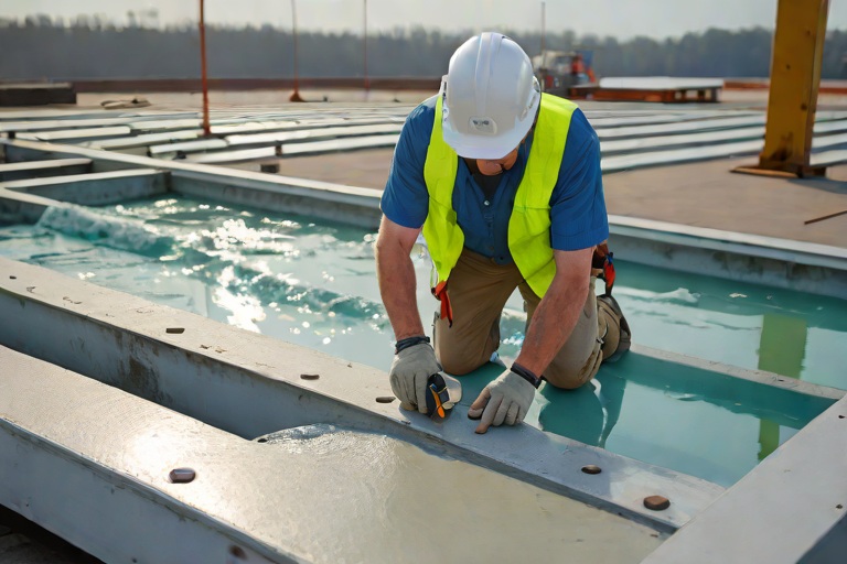
Commercial Engineering Dossier #713

Commercial Kitchen Grease Containment & 304 Stainless Steel Catchment Shielding on Commercial Telecommunications Central Switching Offices

Industrial Building Envelope Sciences • Commercial Low-Slope Systems
Commercial Kitchen Grease Containment & 304 Stainless Steel Catchment Shielding on Commercial Telecommunications Central Switching Offices

The Critical Vulnerability of CSO Building Envelopes to Lipid Contamination

Telecommunications Central Switching Offices (CSOs) represent a unique challenge in building envelope engineering. These facilities are designed for maximum uptime and high-density electronic equipment, often featuring massive HVAC arrays and specialized exhaust systems. A recurring failure point in these structures occurs when commercial-grade kitchen facilities—used for staff dining and 24/7 operations—utilize rooftop exhaust vents that discharge grease-laden air directly over single-ply roofing membranes. This creates a localized environment where animal fat lipids and synthetic oils settle on the roof surface, initiating a slow but relentless chemical degradation of the waterproofing layer.

From a master roofer's perspective, the issue is not merely the accumulation of debris, but the chemical interaction between the lipid deposits and the polymer structure of the membrane. When animal fats oxidize, they create a sticky, acidic film that traps particulates and moisture, effectively turning the roof surface into a chemical reactor. In a CSO environment, where roof access is often restricted due to security protocols, these deposits go unnoticed until the membrane's integrity is compromised, leading to subsurface saturation and potential leaks into sensitive switching equipment below.

  • Atmospheric deposition of aerosolized lipids from commercial kitchen exhaust.
  • Chemical acidification of animal fats leading to pH shifts on the membrane surface.
  • Increased thermal absorption due to the dark, viscous nature of grease accumulation.
  • Accelerated degradation of seam tapes and flashing adhesives.

Material Science of Lipid Degradation on Single-Ply Membranes

The engineering failure begins at the molecular level. Most modern CSOs utilize Thermoplastic Polyolefin (TPO) or Polyvinyl Chloride (PVC) membranes for their reflectivity and ease of installation. However, these materials are susceptible to plasticizer migration when exposed to specific organic solvents and lipids. Animal fats, particularly saturated fats, can act as solvents that leach the plasticizers out of the PVC, leading to embrittlement, shrinkage, and eventually, stress cracking. This process is often accelerated by the high heat associated with kitchen exhaust plumes, which can reach temperatures well above the ambient roof temperature.

Furthermore, the interaction between lipids and TPO membranes often results in "softening" or a tacky surface condition. This attracts atmospheric pollutants and carbon black, which permanently stains the membrane and destroys its Solar Reflectance Index (SRI) rating. Once the lipid layer penetrates the upper wear layer of the membrane, it can migrate into the seams. Since the seams are the most critical point of any roofing system, the degradation of the heat-weld or adhesive bond leads to catastrophic failure during heavy rain events, as the lipid-compromised seal allows for capillary action to draw water directly into the insulation board.

  • Plasticizer migration in PVC leading to loss of flexibility and structural cracking.
  • Surface softening and polymer chain degradation in TPO membranes.
  • Compromised seam integrity resulting in failure to meet ASTM D6877 standards.
  • Increased vulnerability to puncture and mechanical damage due to membrane embrittlement.

Engineering the 304 Stainless Steel Catchment Shielding System

To mitigate these risks, Aquashield Corporate implements a rigorous containment strategy centered on 304 Stainless Steel catchment shielding. We move away from standard galvanized steel, which can corrode under the acidic conditions of oxidized grease, and instead utilize 304 SS for its superior corrosion resistance and non-reactive surface. The engineering goal is to decouple the grease-laden exhaust from the roofing membrane entirely. This is achieved by installing custom-fabricated, oversized catchment boxes directly beneath the exhaust discharge points, creating a physical barrier that intercepts lipids before they can contact the roof.

The design of these shields involves a precision-engineered slope that directs collected lipids toward a removable grease trap or a designated drainage point. The shields are mounted using non-penetrating sleepers to ensure the building envelope remains intact, avoiding the "Swiss cheese" effect of traditional mechanical fasteners. By utilizing a 304 SS shield, we ensure that the containment system can withstand the thermal cycling of the exhaust vent while providing a hygienic, easy-to-clean surface that does not react with the chemical components of the kitchen waste.

  • Fabrication of 304 Stainless Steel shields to prevent galvanic corrosion and lipid reactivity.
  • Implementation of non-penetrating mounting systems to maintain envelope integrity.
  • Integration of removable grease traps for streamlined maintenance and disposal.
  • Strategic sizing of catchment areas to account for wind-drift and plume dispersion.

Sacrificial Coatings and Long-Term Lifecycle Management

While stainless steel shielding provides the primary defense, a comprehensive building envelope audit necessitates a secondary layer of protection. We specify the application of sacrificial, chemical-resistant coatings on the membrane areas surrounding the catchment systems. These coatings, typically high-build polyurea or specialized epoxy resins, are engineered to be chemically inert. They act as a "sacrificial" layer, meaning that any lipids that bypass the stainless steel shields will react with the coating rather than the underlying TPO or PVC membrane.

The lifecycle management of a CSO roof requires a scheduled maintenance program that includes the periodic stripping and re-application of these coatings. By monitoring the thickness and condition of the sacrificial layer, facility managers can predict the remaining useful life of the primary roof membrane. This proactive engineering approach transforms the roof from a passive cover into an active system of containment and protection, ensuring that the critical telecommunications infrastructure below is never compromised by the same facilities that feed the staff.

  • Application of high-build polyurea coatings as a chemical barrier.
  • Scheduled "strip and recoat" cycles to maintain the sacrificial layer.
  • Regular pH testing of the membrane surface to detect early-stage lipid acidification.
  • Alignment with ANSI/NRCA standards for commercial roofing maintenance and inspection.

Aquashield Roofing Corporation

4006 Morris Ct.
Chesapeake, VA 23323
Direct Line: 757-553-5191
GPS Coordinates: 36.755164, -76.353932

Official Facebook Updates

Virginia Beach Roofing Company - Roofing Service Virginia Beach VA, Roofing Contractor

585 S Birdneck Rd #106
Virginia Beach, VA 23451
Direct Line: +17576318100
Google Maps Plus Code: RXCX+V7 Virginia Beach, Virginia
GPS Coordinates: 36.822156, -76.001565
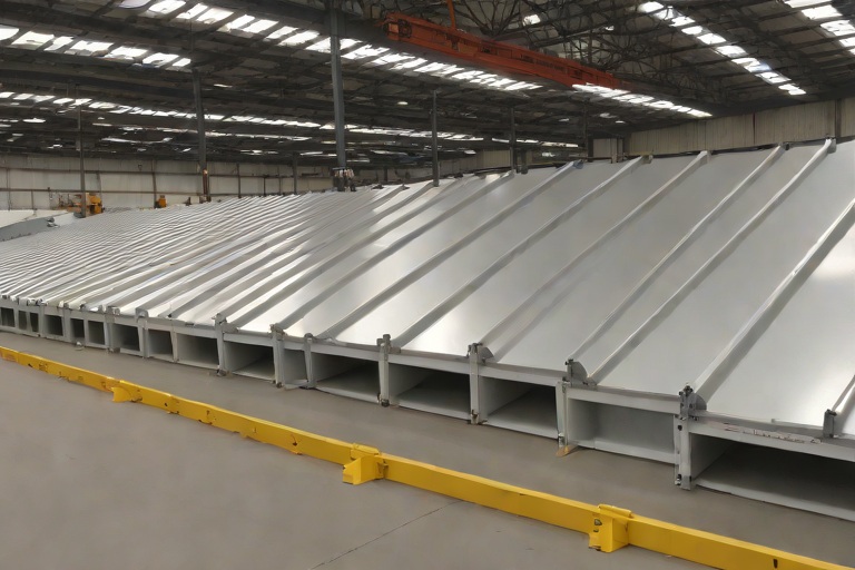
Commercial Engineering Dossier #714

Clear-Span Structural Joist Deflection Forensics & Ponding Instability Remediation on Commercial Heavy Manufacturing Fabrication Plants

Industrial Building Envelope Sciences • Commercial Low-Slope Systems
Clear-Span Structural Joist Deflection Forensics & Ponding Instability Remediation on Commercial Heavy Manufacturing Fabrication Plants

Forensic Analysis of Structural Deflection and Ponding Instability

In the context of heavy manufacturing fabrication plants, the structural integrity of the building envelope is frequently compromised by the inherent physics of clear-span joist systems. When these structures are designed with wide open bays to accommodate overhead cranes and large-scale machinery, the long-span steel joists are susceptible to center-span deflection. This deflection is not merely a structural nuance but the catalyst for a phenomenon known as ponding instability. As the joists sag under dead loads or long-term creep, they create a concave basin that allows rainwater to accumulate. This standing water adds significant hydrostatic weight to the structure, which in turn increases the deflection, creating a vicious cycle of structural deformation and water retention.

From an engineering perspective, we evaluate these failures by analyzing the L/240 or L/360 deflection limits specified in the original structural blueprints. When the actual field measurements exceed these tolerances, the roof ceases to function as a shedding surface and begins to act as a reservoir. This puts immense pressure on the roof membrane, accelerating the degradation of seams and flashing. In a heavy manufacturing environment, where vibration from industrial equipment is constant, this added weight can lead to fatigue in the joist seats and connections, potentially compromising the entire building envelope.

  • Analysis of dead load vs. live load capacities during peak precipitation events.
  • Evaluation of structural creep in long-span steel joists over the building lifecycle.
  • Identification of "ponding basins" where water depth exceeds 1/4 inch after 48 hours of dryness.
  • Assessment of membrane fatigue caused by constant hydrostatic pressure and thermal cycling.

Precision Measurement and Field Audit Protocols

To remediate ponding instability, a master roofer must move beyond visual inspection and employ forensic measurement tools. The audit begins with the establishment of a primary datum point, typically based on the original building height or a known structural column. Using high-precision rotary laser levels and digital transit levels, we map the roof's topography on a grid system. By measuring the vertical distance from the laser plane to the roof surface at 10-foot intervals, we can generate a precise contour map of the center-span deflection. This allows us to quantify the exact volume of water being held in the "belly" of the joists.

This forensic mapping is critical because it distinguishes between a global slope failure and localized depressions. In many fabrication plants, the roof may appear level, but the center-span deflection creates a "hidden" bowl. We utilize string-line tensioning and electronic depth gauges to determine the deepest point of the pond. This data informs the thickness of the remediation materials required to restore a positive slope. Without this quantitative audit, any attempt to fix the roof would be guesswork, likely resulting in new low spots or insufficient drainage.

  • Implementation of a 10' x 10' grid mapping system for topographic analysis.
  • Utilization of rotary laser levels to identify the lowest structural points.
  • Calculation of total water volume retention per square foot of ponded area.
  • Comparison of field-measured deflection against original ANSI/ASTM structural specifications.

Engineering the Remediation: Tapered Polyiso Systems

Once the deflection zones are mapped, the remediation strategy shifts to the installation of custom tapered polyisocyanurate (Polyiso) crickets. Polyiso is the material of choice for this application due to its high compressive strength and superior R-value, which prevents thermal bridging in industrial settings. Unlike traditional screed-to-fall concrete, which adds excessive dead load to already stressed joists, tapered Polyiso provides a lightweight, high-density solution. We engineer these crickets to create a positive slope—typically a minimum of 1/4 inch per foot—directing water away from the center-span depressions and toward the primary drainage points.

The installation process requires a surgical approach to material science. The tapered insulation is cut to precise specifications to ensure a seamless transition from the existing roof deck to the new slope. These crickets act as structural "shims" for the water, forcing it to move laterally across the roof surface. By strategically placing these tapered sections, we effectively "fill" the structural dip without adding significant weight to the joists. This restores the building's ability to shed water rapidly, eliminating the hydrostatic load and stopping the cycle of ponding instability.

  • Selection of high-density Polyiso with a minimum compressive strength of 25 psi.
  • Custom fabrication of tapered insulation panels to match forensic contour maps.
  • Adhesion of insulation using low-VOC, high-strength polymers to ensure wind-uplift resistance.
  • Strategic placement of crickets to eliminate "dead spots" and ensure positive flow.

Final Integration and Envelope Validation

The final phase of the remediation involves the integration of a high-performance roofing membrane over the new tapered system. For heavy manufacturing plants, we typically specify a reinforced TPO (Thermoplastic Polyolefin) or a modified bitumen system, depending on the chemical exposure of the facility. The membrane is heat-welded or adhered to create a monolithic waterproof barrier. Particular attention is paid to the routing of water; we ensure that the new slopes lead directly to oversized scuppers or internal drains, preventing water from backing up at the perimeter walls or flashing details.

To validate the engineering success of the project, we conduct a comprehensive flood test in accordance with ASTM D2197 standards. This involves plugging the drains and filling the previously ponded areas with water to a depth of 2 inches for a minimum of 24 hours. We monitor the structural response and the membrane's integrity. If the water drains rapidly and completely upon releasing the plugs, and no leaks are detected, the envelope is certified. This rigorous validation process ensures that the structural deflection has been neutralized and the building envelope is once again resilient against extreme weather events.

  • Installation of reinforced TPO membranes with heat-welded seams for maximum leak resistance.
  • Optimization of scupper and drain placement to accommodate increased flow rates.
  • Execution of ASTM-standard flood testing to verify positive drainage.
  • Final inspection of flashing and counter-flashing to ensure a watertight transition at all penetrations.

Aquashield Roofing Corporation

4006 Morris Ct.
Chesapeake, VA 23323
Direct Line: 757-553-5191
GPS Coordinates: 36.755164, -76.353932

Official Facebook Updates

Virginia Beach Roofing Company - Roofing Service Virginia Beach VA, Roofing Contractor

585 S Birdneck Rd #106
Virginia Beach, VA 23451
Direct Line: +17576318100
Google Maps Plus Code: RXCX+V7 Virginia Beach, Virginia
GPS Coordinates: 36.822156, -76.001565
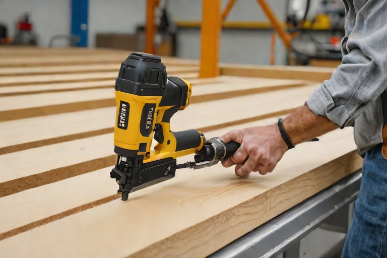
Commercial Engineering Dossier #715

Flute-Fill EPS/Polyiso Insulation Sizing for Standing Rib Metal Roof Retrofits on Commercial Logistics Distribution Hubs

Industrial Building Envelope Sciences • Commercial Low-Slope Systems
Flute-Fill EPS/Polyiso Insulation Sizing for Standing Rib Metal Roof Retrofits on Commercial Logistics Distribution Hubs

The Engineering Challenge of Corrugated Substrates in Logistics Hubs

In the context of large-scale logistics distribution hubs, the building envelope is the primary defense against operational inefficiency and skyrocketing energy costs. During a recent engineering audit conducted for a 500,000-square-foot facility, we identified a critical failure in the existing standing rib metal roof system. The primary issue was not leakage, but rather a systemic failure in thermal continuity. Standing rib profiles, while structurally superior for water shedding, create inherent "thermal voids" within the flutes. When a retrofit is attempted without addressing these voids, the resulting air pockets act as conduits for convective heat transfer, undermining the R-value of the entire assembly.

From a master tradesman's perspective, the challenge lies in the transition from a corrugated profile to a flat, high-performance surface. Most contractors make the mistake of laying insulation boards directly over the ribs, leaving the flutes empty. This creates a "bridge" of insulation that is structurally unstable and thermally compromised. To achieve a true building envelope seal, the engineering focus must shift toward a precision-cut flute-fill strategy that transforms the undulating metal substrate into a monolithic thermal slab.

  • Identification of thermal bypass zones within the standing rib valleys.
  • Analysis of heat flux patterns across large-span metal decking.
  • Evaluation of existing fastener integrity to support additional dead loads.
  • Assessment of the coefficient of thermal expansion between the metal ribs and the insulation.

Precision-Cut Flute-Fill Geometry and Material Selection

The core of the Aquashield approach involves the deployment of CNC-precision cut flute-fill profiles. We utilize a hybrid material strategy, leveraging the compressive strength of Expanded Polystyrene (EPS) and the superior thermal resistance of Polyisocyanurate (Polyiso). The EPS is typically employed as the base "filler" to lock into the geometry of the rib, while the Polyiso provides the primary thermal barrier. This ensures that the insulation is not merely sitting on the roof, but is mechanically integrated into the profile of the metal deck.

Precision is non-negotiable. A gap of even one-quarter inch between the flute-fill insert and the metal rib can lead to significant air infiltration and localized condensation. By utilizing digital templates of the specific rib profile—whether it be a sinusoidal or a trapezoidal standing rib—we ensure a friction-fit tolerance that eliminates the need for excessive adhesives. This method adheres to ASTM C1285 standards for thermal insulation in commercial roofing, ensuring that the material density is sufficient to withstand the compressive forces of the final membrane installation.

  • Utilization of CNC-routed Polyiso for exact rib-matching.
  • Application of high-density EPS for structural stability in deep-flute profiles.
  • Implementation of a staggered joint layout to prevent linear thermal leaking.
  • Verification of material thickness to ensure a perfectly flush top-of-insulation (TOI) elevation.

Mitigating Thermal Bridging and Air Infiltration

Thermal bridging occurs when a highly conductive material, such as the steel of a standing rib roof, creates a path for heat to bypass the insulation. In a logistics hub, where internal temperatures must be regulated for worker safety and inventory preservation, these bridges are catastrophic. The metal ribs act as thermal fins, drawing heat out of the building in winter and pumping it in during summer. By filling the flutes entirely, we effectively "break" the bridge, forcing the heat flow to move through the insulation rather than the steel.

Furthermore, the integration of a continuous air and vapor barrier is essential. We specify the installation of a high-performance vapor retarder beneath the flute-fill inserts. This prevents moisture-laden air from the warehouse interior from migrating into the insulation voids, where it would otherwise condense against the cold metal of the ribs. This holistic approach to the building envelope ensures that the assembly functions as a single, airtight unit rather than a collection of disparate materials.

  • Elimination of "point-source" heat loss at the rib peaks.
  • Reduction of convective loops within the roof assembly.
  • Installation of closed-cell sealants at the perimeter of the flute-fill zones.
  • Compliance with ANSI standards for commercial building envelope airtightness.

Membrane Integration and Final Assembly Sequence

Once the flute-fill inserts are locked in and the roof surface is leveled, the final phase is the installation of a flat, single-ply membrane. We typically recommend a reinforced TPO (Thermoplastic Polyolefin) or PVC membrane for logistics hubs due to their superior puncture resistance and weldability. The transition from the filled flutes to the membrane is the most critical point of the installation; any unevenness in the flute-fill height will result in "telegraphing," where the rib pattern is visible through the membrane, creating potential stress points and premature failure.

The membrane is mechanically fastened or fully adhered depending on the wind-uplift requirements of the region. By creating a flat plane via the flute-fill method, we allow for a consistent application of the membrane, ensuring that the seams are welded with uniform heat and pressure. This results in a roof system that is not only thermally efficient but also structurally resilient against the extreme weather conditions typical of large-span commercial buildings. The final audit confirms a significant reduction in HVAC load and a total elimination of the thermal bridging previously identified.

  • Application of a separation layer to protect the Polyiso from membrane adhesives.
  • Hot-air welding of TPO seams to ensure a watertight, monolithic seal.
  • Installation of heavy-duty flashing at the parapet and curb interfaces.
  • Final infrared thermography scan to verify the absence of remaining thermal bridges.

Aquashield Roofing Corporation

4006 Morris Ct.
Chesapeake, VA 23323
Direct Line: 757-553-5191
GPS Coordinates: 36.755164, -76.353932

Official Facebook Updates

Virginia Beach Roofing Company - Roofing Service Virginia Beach VA, Roofing Contractor

585 S Birdneck Rd #106
Virginia Beach, VA 23451
Direct Line: +17576318100
Google Maps Plus Code: RXCX+V7 Virginia Beach, Virginia
GPS Coordinates: 36.822156, -76.001565

Commercial Engineering Dossier #716

Structural Plywood Deck Re-Nailing Schedules on Commercial Automotive Assembly Plants

Industrial Building Envelope Sciences • Commercial Low-Slope Systems
Structural Plywood Deck Re-Nailing Schedules on Commercial Automotive Assembly Plants

Engineering Audit of Coastal Wind Uplift and Diaphragm Integrity

In the high-stakes environment of a commercial automotive assembly plant, the roof is not merely a cover but a critical structural diaphragm. During our recent engineering audit for Aquashield Corporate, we focused on a facility situated in a coastal high-wind zone, where the building envelope is subject to extreme pressure differentials. The primary concern in these regions is the phenomenon of wind uplift, where low-pressure zones created by high-velocity winds effectively attempt to peel the roofing system away from the structural steel and wood decking. For an automotive plant, where internal climate control and dust mitigation are paramount, any failure in the plywood deck attachment can lead to catastrophic envelope breach.

Our analysis began with a review of the existing ASCE 7 wind load calculations. In coastal regions, the wind speed requirements necessitate a more aggressive fastening schedule than standard inland commercial builds. We identified that the original installation lacked the necessary fastener density to resist the calculated uplift forces. When the plywood deck is not properly secured, the assembly loses its shear strength, allowing the panels to shift or lift, which in turn compromises the membrane above and the structural integrity of the roof joists below.

  • Evaluation of peak gust wind speeds and their correlation to roof-zone pressure coefficients.
  • Assessment of existing fastener spacing against current International Building Code (IBC) standards.
  • Identification of "critical zones" at the roof corners and perimeters where turbulence is highest.
  • Analysis of the load path from the roof membrane down to the primary structural steel frames.

Material Science of Pneumatically Driven Ring-Shank Fasteners

To rectify the deficiencies found during the audit, we specified a comprehensive re-nailing program utilizing pneumatically driven ring-shank fasteners. From a material science perspective, the ring-shank nail is vastly superior to the smooth-shank alternative in high-wind applications. The rings act as mechanical anchors, creating a series of "locks" within the wood fibers of the plywood and the supporting joists. This creates a significantly higher withdrawal resistance, as the nail cannot be pulled straight out without physically crushing the wood cells it has gripped.

The use of pneumatic nailers is not merely for speed, but for consistency of embedment. A master tradesman knows that the depth of the nail head is critical; over-driving a nail can crush the plywood face, reducing the effective thickness of the deck and creating a "dish" that traps moisture. Conversely, under-driving leaves the fastener prone to vibration-induced backing. We calibrated our pneumatic equipment to ensure a consistent flush-set, ensuring that the fastener head provides maximum clamping force without compromising the structural integrity of the plywood ply.

  • Utilization of ASTM F1667 compliant ring-shank nails for enhanced grip and pull-out resistance.
  • Calibration of pneumatic pressure to prevent "blow-through" or over-penetration of the substrate.
  • Implementation of galvanized coatings to prevent galvanic corrosion in salty coastal air.
  • Verification of nail diameter and gauge to ensure optimal shear capacity across the wood grain.

Re-Nailing Schedules and Shear Withdrawal Resistance

The core of our engineering solution was the implementation of a rigorous re-nailing schedule designed to maximize shear withdrawal resistance. Shear withdrawal occurs when the lateral force of the wind attempts to slide the plywood panel across the top of the joist. By increasing the frequency of fasteners, we distribute the wind load across a larger number of points, reducing the stress on any single nail. Our schedule focused on a tiered approach, recognizing that the perimeter of the automotive plant experiences significantly higher stress than the center of the roof.

We mandated a 6-inch on-center (O.C.) spacing for all perimeter and edge panels, transitioning to a 12-inch O.C. spacing in the field. This strategic density ensures that the roof acts as a monolithic slab, effectively transferring lateral loads to the building's primary structural frame. We specifically targeted the "edge-of-panel" zones, as these are the most common points of failure during a wind event. By doubling the fastener count at these critical junctions, we ensured that the diaphragm action of the plywood remained intact even under peak pressure loads.

  • Perimeter Zone: 6" O.C. fastening to resist maximum edge-lift forces.
  • Field Zone: 12" O.C. fastening to maintain general diaphragm stability.
  • Corner Zones: Specialized reinforced fastening patterns to combat vortex shedding.
  • Verification of fastener penetration depth to ensure full engagement with the structural member.

Building Envelope Verification and Quality Assurance

The final phase of the Aquashield Corporate audit involved a rigorous verification process to ensure the re-nailing schedule was executed to master-level standards. A building envelope is only as strong as its weakest point; therefore, we employed a random sampling method to test the shear withdrawal resistance of the installed fasteners. Using a calibrated pull-tester, we verified that the ring-shank nails met or exceeded the required poundage for withdrawal before failure. This empirical data provided the necessary engineering assurance that the roof could withstand the projected coastal wind loads.

Beyond the fasteners, we examined the overall health of the plywood deck, checking for delamination or moisture intrusion that could soften the wood fibers and reduce the nail's holding power. The integration of the re-nailing process with the final membrane application ensured a seamless transition from the structural deck to the weather-tight envelope. By treating the roof as a holistic system—from the ring-shank nail in the joist to the final seam of the membrane—we provided the automotive plant with a structural lifespan extension and a significant reduction in risk.

  • Randomized pull-tests to quantify actual versus theoretical withdrawal resistance.
  • Visual inspection of all nail heads to ensure flush-set installation across 100% of the deck.
  • Moisture mapping of the plywood substrate to identify areas requiring additional blocking.
  • Final sign-off on the building envelope audit, confirming compliance with coastal wind standards.

Aquashield Roofing Corporation

4006 Morris Ct.
Chesapeake, VA 23323
Direct Line: 757-553-5191
GPS Coordinates: 36.755164, -76.353932

Official Facebook Updates

Virginia Beach Roofing Company - Roofing Service Virginia Beach VA, Roofing Contractor

585 S Birdneck Rd #106
Virginia Beach, VA 23451
Direct Line: +17576318100
Google Maps Plus Code: RXCX+V7 Virginia Beach, Virginia
GPS Coordinates: 36.822156, -76.001565
Commercial Engineering Dossier #717

Life-Cycle Cost Analysis (LCCA) on Commercial Mission-Critical Data Centers

Industrial Building Envelope Sciences • Commercial Low-Slope Systems
Life-Cycle Cost Analysis (LCCA) on Commercial Mission-Critical Data Centers

The Engineering Audit and Envelope Integrity for Mission-Critical Assets

In the realm of mission-critical data centers, the building envelope is not merely a shell; it is the primary defense system for millions of dollars in computing hardware and sensitive electrical infrastructure. A comprehensive engineering audit begins with a forensic analysis of the roof assembly, focusing on the transition points where the most frequent failures occur. We evaluate the substrate for moisture saturation and the integrity of the flashing at all penetrations, ensuring compliance with ASTM E2128 standards for moisture detection. In a data center, a single breach in the envelope can lead to catastrophic downtime, making the "zero-leak" threshold a non-negotiable requirement.

Our approach focuses on the physics of the building envelope, specifically the management of vapor drive and thermal expansion. Data centers generate immense internal heat, creating a significant temperature gradient between the interior and the exterior roof surface. This thermal stress can lead to premature fatigue in membranes and the failure of sealant joints. By utilizing infrared thermography and moisture scanning, we identify subsurface anomalies before they manifest as active leaks, allowing for a surgical approach to restoration rather than a blind replacement.

  • Assessment of membrane tensile strength and elasticity to prevent stress cracking.
  • Evaluation of drainage efficiency to eliminate ponding water, which accelerates membrane degradation.
  • Inspection of parapet wall flashing and coping caps to prevent lateral water infiltration.
  • Analysis of HVAC curb seals and penetration points for airtightness and water-tightness.
  • Verification of R-value performance to optimize the facility's cooling efficiency.

Net Present Value (NPV) and Life-Cycle Cost Analysis

When presenting a Life-Cycle Cost Analysis (LCCA) to stakeholders, the conversation must shift from the initial ticket price to the Net Present Value (NPV). A traditional "rip-and-replace" strategy often appears attractive because it resets the clock to zero, but it ignores the massive costs associated with demolition, disposal, and the risk of operational disruption. By calculating the NPV, we compare the total cost of ownership over a 20-year horizon, discounting future costs back to today's dollars to determine the most economically viable path.

The financial model for a high-performance restoration typically outperforms a full replacement. By utilizing advanced material science—such as high-solids silicone or PMMA coatings—we can extend the life of the existing asset without the volatility of a full tear-off. The NPV calculation accounts for the avoidance of future replacement costs, the reduction in energy expenditure due to increased solar reflectivity (SRI), and the elimination of the "replacement cycle" every 15 years. This transforms the roof from a recurring liability into a managed asset.

  • Calculation of the Internal Rate of Return (IRR) for restoration versus replacement.
  • Analysis of the "Cost of Failure" associated with potential leaks in a data center environment.
  • Comparison of initial capital outlay against long-term maintenance reductions.
  • Evaluation of energy savings derived from Cool Roof technology and Albedo effect.
  • Projection of asset longevity through the application of reinforced membrane systems.

Tax Deductions for Maintenance Restoration and Capital Strategy

One of the most overlooked advantages of a building envelope restoration is the distinction between a capital improvement and a maintenance expense. Under many tax codes, a full roof replacement is classified as a capital expenditure (CapEx), which must be depreciated over the useful life of the building—often 39 years for commercial structures. This delays the financial benefit of the investment. Conversely, a professional restoration that restores the roof to its original design intent can often be classified as a maintenance expense (OpEx).

By categorizing the project as maintenance restoration, the organization can potentially deduct the entire cost of the project in the current tax year. This provides an immediate cash-flow advantage and significantly improves the project's NPV. As a master roofer, I ensure that the engineering documentation clearly defines the scope as "restoration of function" rather than "addition of value," providing the necessary technical justification for the accounting department to maximize these tax deductions.

  • Differentiation between Section 179 immediate expensing and long-term depreciation.
  • Documentation of existing substrate viability to justify the restoration approach.
  • Analysis of the tax impact of "Repair and Maintenance" versus "Capital Improvement."
  • Strategic timing of restoration cycles to align with corporate fiscal year goals.
  • Reduction of the overall tax liability through sustainable building certifications.

Sustainability, Landfill Mitigation, and 15-Year Warranty Extensions

The environmental impact of commercial roofing is staggering. A full tear-off of a large-scale data center roof results in hundreds of tons of thermoplastic or modified bitumen waste heading directly to a landfill. This not only contradicts corporate ESG (Environmental, Social, and Governance) goals but also increases the project's carbon footprint through the transport of waste and the manufacturing of new materials. Our engineering focus is on "in-place" restoration, which effectively eliminates the need for landfill disposal by utilizing the existing roof as a structural base.

To provide the necessary security for mission-critical assets, we implement 15-year warranty extensions. These are not standard labor warranties; they are comprehensive material and workmanship guarantees backed by rigorous ASTM testing. By applying a multi-layer system of primers and high-performance membranes, we create a monolithic seal that is impervious to UV degradation and chemical pollutants. This extension of the asset's life ensures that the facility manager can lock in the building's envelope integrity for over a decade, removing the uncertainty of future leaks and the associated risks to the data center's uptime.

  • Reduction of VOC emissions by utilizing low-solvent, high-solids coating systems.
  • Elimination of landfill waste by avoiding the removal of existing membrane layers.
  • Implementation of high-reflectivity surfaces to mitigate the Urban Heat Island effect.
  • Rigorous quality control audits to ensure the 15-year warranty criteria are met.
  • Long-term monitoring of the envelope to ensure continued performance and compliance.

Aquashield Roofing Corporation

4006 Morris Ct.
Chesapeake, VA 23323
Direct Line: 757-553-5191
GPS Coordinates: 36.755164, -76.353932

Official Facebook Updates

Virginia Beach Roofing Company - Roofing Service Virginia Beach VA, Roofing Contractor

585 S Birdneck Rd #106
Virginia Beach, VA 23451
Direct Line: +17576318100
Google Maps Plus Code: RXCX+V7 Virginia Beach, Virginia
GPS Coordinates: 36.822156, -76.001565
Commercial Engineering Dossier #718

Lightning Protection System Air Terminal Stanchion Flashing & Membrane Bonding on Commercial Cold Storage Freezer Warehouses

Industrial Building Envelope Sciences • Commercial Low-Slope Systems
Lightning Protection System Air Terminal Stanchion Flashing & Membrane Bonding on Commercial Cold Storage Freezer Warehouses

The Thermal Dynamics of Cold Storage Penetrations

In the specialized field of commercial building envelope engineering, cold storage freezer warehouses represent one of the most challenging environments for a roofing professional. These structures are essentially massive thermal batteries, maintaining internal temperatures often as low as -20°F while exposed to fluctuating external ambient conditions. This extreme temperature differential creates a powerful vapor drive, where moisture from the warm exterior air relentlessly attempts to migrate toward the cold interior. When we introduce a Lightning Protection System (LPS), specifically air terminal stanchions, we are creating intentional penetrations through the most critical layer of the building's defense: the roof membrane.

The primary risk in these installations is the creation of a thermal bridge. A metal stanchion, if not properly isolated, acts as a highly efficient conductor of heat and cold. In a freezer warehouse, this can lead to localized condensation or "sweating" on the interior side of the roof deck. If moisture accumulates around the penetration point, it can freeze, leading to ice lensing and subsequent mechanical stress on the membrane. To maintain the integrity of the building envelope, the engineering focus must shift from simple waterproofing to a comprehensive approach involving thermal breaks and airtight seals.

  • Management of the dew point to prevent interstitial condensation within the roof assembly.
  • Mitigation of thermal bridging using non-conductive spacers or high-density insulation collars.
  • Control of vapor transmission to prevent moisture from infiltrating the polyisocyanurate insulation layers.
  • Evaluation of the coefficient of thermal expansion between the metal LPS components and the thermoplastic membrane.

Advanced Stanchion Pitch-Pocket Engineering

Traditional flashing boots are often insufficient for the heavy-duty requirements of a commercial freezer warehouse. Instead, we implement a reinforced pitch-pocket detail. A pitch-pocket is a custom-fabricated metal housing that encapsulates the base of the air terminal stanchion, providing a secondary containment system for moisture. This detail ensures that even if the primary membrane seal is compromised, the water is captured and diverted away from the roof deck. From an engineering perspective, the pitch-pocket must be seamlessly integrated into the roof's drainage plane to avoid ponding.

The internal sealing of the pocket requires a multi-stage approach. We begin with a high-performance flashing membrane, followed by the application of a non-sagging, polymer-modified sealant that remains flexible at extreme temperatures. The sealant must be compatible with both the metal of the stanchion and the chemical composition of the roof membrane (whether TPO, PVC, or EPDM). Failure to use a chemically compatible sealant leads to adhesive failure, which, under the stress of thermal cycling, opens a direct path for water ingress.

  • Utilization of heavy-gauge galvanized or stainless steel for the pocket housing to prevent premature corrosion.
  • Application of liquid-applied flashing membranes to create a monolithic, seamless bond around the stanchion base.
  • Implementation of a "double-dam" sealant strategy to ensure redundant waterproofing layers.
  • Strict adherence to ASTM standards for flashing installation and compression strength.

Conductor Routing and Membrane Bonding Protocols

The grounding cable conductors that connect the air terminals to the building's grounding grid are often overlooked, yet they represent a significant vulnerability. These cables are typically fastened to the roof surface using clips or adhesives. In a cold storage environment, the roof membrane undergoes significant expansion and contraction. If the conductors are fastened too rigidly, the resulting mechanical tension can tear the membrane or pull the fasteners through the substrate, creating "micro-punctures" that are nearly impossible to detect during a standard walk-through.

To solve this, we employ a floating conductor strategy. Instead of rigid fastening, the cables are routed with calculated slack—expansion loops—that allow the roof to move independently of the LPS hardware. Furthermore, the bonding of these conductors to the membrane is achieved using wide-profile bonding strips. These strips distribute the load across a larger surface area, reducing the point-load stress on the membrane. This approach ensures that the conductor remains secure during high-wind events while preserving the puncture-resistance of the envelope.

  • Installation of expansion loops at every 20 feet of conductor run to accommodate thermal movement.
  • Use of UV-stabilized bonding adhesives to prevent degradation from solar radiation.
  • Avoidance of sharp 90-degree bends in the conductor, which can create stress concentrations on the membrane.
  • Verification of cable tension using calibrated torque tools to ensure fasteners are not over-compressed.

Forensic Analysis of Lightning-Induced Membrane Failure

The most catastrophic failure in an LPS installation occurs during a strike event. A lightning bolt carries an immense amount of electrical energy, which is converted into heat upon impact. If the air terminal is not properly bonded and the grounding path is inefficient, the resulting arc can cause "blow-out" failures. This occurs when the electrical discharge jumps from the conductor to the roof deck, instantly vaporizing the thermoplastic membrane and creating a hole that allows water and air to flood the freezer warehouse.

Our engineering audits focus on the "arc-gap" prevention. By ensuring that the stanchion is perfectly vertical and the bonding is seamless, we minimize the chance of side-flashing. Furthermore, we analyze the material science of the membrane; for instance, PVC membranes have different dielectric properties than TPO. We recommend the use of conductive-resistant flashing materials at the point of entry to dissipate the heat of a strike more evenly across the surface, preventing the localized melting of the roofing system.

  • Conducting infrared thermography after a strike to identify hidden "burn-through" points in the insulation.
  • Testing the electrical continuity of the grounding path to ensure the lowest possible impedance.
  • Evaluating the integrity of the membrane's weld lines near the stanchion to ensure no heat-induced embrittlement.
  • Implementing a quarterly audit schedule to check for vibration-induced wear at the conductor-membrane interface.

Aquashield Roofing Corporation

4006 Morris Ct.
Chesapeake, VA 23323
Direct Line: 757-553-5191
GPS Coordinates: 36.755164, -76.353932

Official Facebook Updates

Virginia Beach Roofing Company - Roofing Service Virginia Beach VA, Roofing Contractor

585 S Birdneck Rd #106
Virginia Beach, VA 23451
Direct Line: +17576318100
Google Maps Plus Code: RXCX+V7 Virginia Beach, Virginia
GPS Coordinates: 36.822156, -76.001565

Commercial Engineering Dossier #719

Commercial Roof Hatch Safety Grab Bars & Compression Curb Gasket Weatherproofing on Commercial Commercial Fleet Maintenance Hangars

Industrial Building Envelope Sciences • Commercial Low-Slope Systems
Commercial Roof Hatch Safety Grab Bars & Compression Curb Gasket Weatherproofing on Commercial Commercial Fleet Maintenance Hangars

Structural Integrity and OSHA Compliance for Roof Access Systems

In the high-stakes environment of a commercial fleet maintenance hangar, the roof is more than just a weather barrier; it is a critical operational platform. When conducting a building envelope audit, the primary point of failure often begins at the roof hatch. For fleet hangars, which typically feature expansive clear-span roofing and significant heights, the transition from a fixed ladder to the roof surface represents a high-risk zone. To mitigate these risks, we implement OSHA-compliant ladder safety posts and integrated grab bars that exceed standard building codes.

The engineering focus here is on lateral stability and tensile strength. A standard hatch opening without proper safety extensions forces the technician to climb above the roofline and "pull" themselves onto the deck, which creates a dangerous center-of-gravity shift. By installing heavy-duty, powder-coated steel grab bars that extend 42 inches above the roof surface, we ensure a secure three-point contact during the transition. These posts must be mechanically fastened directly to the structural curb, not merely the flashing, to prevent shearing under the load of a technician carrying tools.

  • Installation of 1.5-inch schedule 40 steel piping for grab bars to ensure zero deflection during use.
  • Compliance with OSHA 1910.28 standards regarding fall protection and secure access points.
  • Utilization of high-torque fasteners with oversized load-spreading washers to prevent curb deformation.
  • Application of safety-yellow powder coating for high visibility against dark EPDM or TPO membranes.

Atmospheric Pressure and Counterbalanced Smoke Damper Integration

Fleet maintenance hangars are unique due to their massive internal volumes and the presence of heavy exhaust systems. This creates complex internal pressure dynamics. When a roof hatch is integrated with a smoke damper system, the engineering must account for both fire safety and the integrity of the building envelope. Counterbalanced smoke dampers are essential because they allow for rapid evacuation of smoke while maintaining a tight seal during normal operations to prevent conditioned air loss.

From a material science perspective, the failure point in these systems is typically the seal interface where the damper meets the curb. If the counterbalancing is improperly calibrated, the damper may "flutter" or fail to seat fully, creating a vacuum effect that pulls moisture from the roof surface into the building interior. We specify dampers with high-temperature silicone seals that maintain elasticity across a wide thermal range, ensuring that the building envelope remains airtight regardless of the internal hangar temperature or external atmospheric pressure.

  • Calibration of counterweight systems to ensure a positive seal without requiring excessive manual force.
  • Integration of smoke-activated actuators that interface with the building's central fire alarm system.
  • Use of reinforced galvanized steel frames to prevent warping under extreme heat conditions.
  • Implementation of perimeter weather-stripping to eliminate air infiltration and energy inefficiency.

High-Compression Curb Gasket Engineering and Material Science

The interface between the roof hatch curb and the primary roofing membrane is the most vulnerable point for water infiltration. In a fleet hangar, where thermal expansion and contraction are magnified by the sheer size of the roof, a standard bead of sealant is insufficient. We utilize heavy-duty compression curb gaskets designed to create a permanent, watertight seal through mechanical pressure rather than chemical adhesion alone.

The science of the "compression set" is critical here. We specify closed-cell EPDM or silicone gaskets that possess a high memory—meaning they return to their original shape after being compressed. When the hatch curb is bolted down, the gasket is compressed to approximately 30% of its original thickness, creating a high-pressure seal that conforms to the irregularities of the roof deck. This prevents the "capillary action" that often draws water upward into the curb assembly during heavy rain events or snow accumulation.

  • Selection of gaskets with a Shore A hardness rating that balances compressibility with structural support.
  • Application of a dual-layer sealing strategy: a primary compression gasket and a secondary liquid-applied flashing.
  • Analysis of thermal bridging to ensure the gasket does not create a cold spot that leads to internal condensation.
  • Verification of ASTM standards for water penetration resistance under simulated wind-driven rain conditions.

Termination Bar Mechanics and Long-Term Envelope Sealing

To finalize the building envelope at the hatch perimeter, we employ compression termination bars. A termination bar is a rigid metal strip that mechanically locks the roofing membrane against the vertical face of the curb. In a professional engineering application, the goal is to eliminate any possibility of the membrane "bridging" or pulling away from the curb, which is a common failure in lower-quality installations.

The process involves a "sandwich" technique: the membrane is adhered to the curb, a neoprene gasket is placed behind the termination bar, and the bar is then fastened with stainless steel fasteners at 6-inch intervals. This creates a continuous line of pressure that forces the membrane into the substrate. By utilizing a compression bar, we distribute the clamping force evenly across the entire width of the flashing, preventing the localized stress points that lead to tears in the TPO or PVC membrane over time. This rigorous approach ensures that the hangar remains watertight for the duration of its service life, protecting the expensive fleet assets housed below.

  • Use of 0.125-inch thick galvanized steel termination bars to provide maximum rigidity and prevent bowing.
  • Installation of neoprene gaskets behind the bars to provide a secondary water-stop and vibration dampening.
  • Application of a high-solids acrylic sealant over the top edge of the bar to prevent water from entering the fastener holes.
  • Strict adherence to a staggered fastening pattern to ensure uniform tension across the membrane surface.

Aquashield Roofing Corporation

4006 Morris Ct.
Chesapeake, VA 23323
Direct Line: 757-553-5191
GPS Coordinates: 36.755164, -76.353932

Official Facebook Updates

Virginia Beach Roofing Company - Roofing Service Virginia Beach VA, Roofing Contractor

585 S Birdneck Rd #106
Virginia Beach, VA 23451
Direct Line: +17576318100
Google Maps Plus Code: RXCX+V7 Virginia Beach, Virginia
GPS Coordinates: 36.822156, -76.001565

Previous (Vol. 17) Volume 18 of 23 (40 Dossiers / Page) Next (Vol. 19)