Aquashield Corporate Shield Logo

AQUASHIELD CORPORATE

Commercial Flat Roofing & Industrial Facility Engineering

A comprehensive technical compendium on commercial 60-mil TPO single-ply systems, high-solids silicone restorative coatings, and building envelope preservation. Volume 3 of 23.

Previous (Vol. 2) Volume 3 of 23 (40 Dossiers / Page) Next (Vol. 4)
Commercial Engineering Dossier #080

Complete Old Roof Tear-Offs Down to Clean Wood Decking & Substrate Remediation on Commercial Port Marine Shipping Warehouses
Industrial Building Envelope Sciences • Commercial Low-Slope Systems
Complete Old Roof Tear-Offs Down to Clean Wood Decking & Substrate Remediation on Commercial Port Marine Shipping Warehouses

Engineering Audit and Failure Analysis of Legacy Marine Assemblies

In the high-salinity, high-humidity environment of a port marine shipping warehouse, the building envelope is under constant chemical and physical assault. Our engineering audit began with a comprehensive forensic analysis of the existing roof assembly, which had evolved into a problematic "roofing sandwich." Over several decades, previous contractors had opted for recoveries rather than full tear-offs, resulting in multiple layers of built-up roofing (BUR) and modified bitumen. This layering created a massive thermal mass that trapped moisture and accelerated the degradation of the underlying structural wood decking.

The failure mechanism was primarily driven by hygrothermal imbalances. Moisture infiltrated through aged flashing and perimeter seams, becoming trapped between the impermeable bitumen layers. Because the moisture could not evaporate, it migrated downward via capillary action, saturating the wood substrate. This created a permanent state of dampness, leading to the breakdown of cellulose fibers and the onset of fungal decay. Our audit utilized infrared thermography and moisture probes to map the saturation levels across the warehouse footprint, identifying critical zones where the structural integrity of the deck had been compromised.

  • Evaluation of multi-layer bitumen buildup and its impact on dead-load structural calculations.
  • Identification of flashing failures at parapet walls and HVAC curb penetrations.
  • Analysis of salt-spray crystallization within the substrate, which accelerates wood rot.
  • Assessment of vapor drive and the failure of legacy vapor barriers to protect the interior envelope.

Strategic Deconstruction and the Mechanics of Total Tear-Off

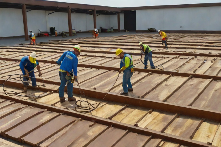
The objective of the deconstruction phase was not merely removal, but the surgical exposure of the structural deck to allow for an honest engineering assessment. A total tear-off is the only viable path when the substrate has been subjected to long-term moisture entrapment. We employed heavy-duty mechanical removal equipment, ensuring that the removal process did not introduce further mechanical damage to the aged wood decking. The process required a systematic approach to avoid overloading specific sections of the roof during the staging of debris, as the saturated wood had a reduced load-bearing capacity.

Precision is paramount during the final stage of the tear-off. The transition from mechanical removal to manual scraping ensures that all residual adhesives and bitumen fragments are eliminated. A "clean deck" is defined as a substrate free of old fasteners, nails, and asphaltic residue. This is critical because any remaining bitumen can act as a contaminant, preventing new membranes from bonding correctly or creating uneven points of pressure that lead to premature membrane puncture. We adhered to strict ANSI safety standards for fall protection and debris containment, given the warehouse's proximity to active shipping lanes.

  • Utilization of specialized scraping tools to remove tenacious bitumen adhesives without gouging the wood.
  • Implementation of a phased removal sequence to maintain the building's weather-tightness in sections.
  • Strict waste management protocols to handle hazardous legacy materials and asphaltic waste.
  • Verification of fastener removal to prevent "ghosting" or protrusions in the new assembly.

Structural Substrate Evaluation and Wood Decking Remediation

Once the substrate was fully exposed, we conducted a detailed structural audit of the wood decking. In a marine warehouse environment, wood is susceptible to "wet rot" and "dry rot" (brown rot), where the structural lignin is consumed by fungi. We utilized a probe-and-measure technique to determine the depth of decay. Any panel exhibiting more than 15% loss of structural thickness or showing signs of delamination was flagged for immediate remediation. The focus was on ensuring that the deck could once again support the intended live loads and the dead load of the new high-performance roofing system.

Remediation involved the surgical removal of damaged panels and the installation of new, marine-grade structural plywood or OSB, depending on the original specification and current engineering requirements. We ensured that new panels were installed with a 1/8-inch gap to allow for natural thermal expansion and contraction, preventing the "buckling" effect common in poorly installed commercial decks. All new panels were secured using heavy-duty, corrosion-resistant fasteners, ensuring a tight mechanical bond to the underlying joists and rafters. This process restored the diaphragm strength of the roof, which is essential for the building's overall lateral stability against high coastal winds.

  • Moisture content (MC) testing to ensure new wood is within the acceptable range for membrane application.
  • Replacement of decayed blocking and perimeter nailers to ensure a secure flashing base.
  • Application of wood preservatives to treated areas to inhibit future fungal growth.
  • Verification of structural load-bearing capacity through a certified engineer's review of the remediated sections.

Implementing the High-Performance Building Envelope Recovery

The final phase of the project focused on the installation of a modern, engineered building envelope designed for the rigors of a port environment. With a clean and remediated substrate, we were able to install a high-performance vapor barrier and a multi-ply modified bitumen system with a granulated cap sheet for UV protection. The material science behind the new assembly focuses on flexibility and impermeability. We utilized a reinforced polyester matting that provides superior puncture resistance and accommodates the slight movements inherent in large-scale warehouse structures.

Crucial attention was paid to the "critical junctions"—the corners, drains, and wall transitions. We implemented a redundant flashing system, utilizing reinforced flashing membranes that are heat-welded to the primary field. This eliminates the reliance on adhesives alone, which can fail in extreme temperature fluctuations. The result is a monolithic envelope that protects the structural wood decking from the elements while allowing the building to breathe according to the calculated vapor drive of the interior space. This comprehensive approach transforms the roof from a liability into a long-term asset, ensuring the warehouse remains operational for decades to come.

  • Installation of a high-density vapor retarder to prevent interior moisture from migrating into the deck.
  • Application of a heat-welded membrane system to ensure seamless water-tightness.
  • Integration of heavy-duty edge metal flashing to prevent wind-uplift and water infiltration at the perimeter.
  • Final flood testing of the assembly to verify the integrity of all seams and penetrations.

Aquashield Roofing Corporation

4006 Morris Ct.
Chesapeake, VA 23323
Direct Line: 757-553-5191
GPS Coordinates: 36.755164, -76.353932

Official Facebook Updates

Virginia Beach Roofing Company - Roofing Service Virginia Beach VA, Roofing Contractor

585 S Birdneck Rd #106
Virginia Beach, VA 23451
Direct Line: +17576318100
Google Maps Plus Code: RXCX+V7 Virginia Beach, Virginia
GPS Coordinates: 36.822156, -76.001565

Commercial Engineering Dossier #081

Stripping Old Shingles Down to Clean Wood Sheathing Across Commercial Eaves on Commercial Municipal Sports & Convention Arenas

Industrial Building Envelope Sciences • Commercial Low-Slope Systems
Stripping Old Shingles Down to Clean Wood Sheathing Across Commercial Eaves on Commercial Municipal Sports & Convention Arenas

The Systematic Deconstruction of Legacy Roofing Systems

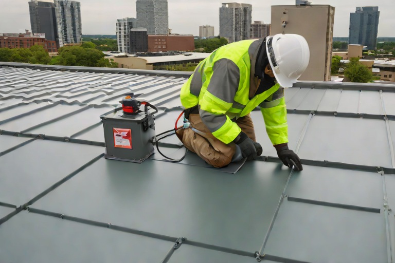
In the context of municipal sports and convention arenas, the building envelope is frequently compromised by the historical practice of "layering" or "roofing over" existing shingles. From an engineering perspective, this creates a cumulative dead load that often exceeds the original design specifications of the roof trusses. An authoritative audit begins with a comprehensive stripping process, removing every layer of legacy asphalt and felt until the original wood sheathing is exposed. This is not merely a demolition task but a forensic extraction intended to reveal the true condition of the structural deck.

The removal process must be executed with precision to avoid damaging the underlying sheathing. When dealing with multi-layer systems, the bond between old asphalt and the wood often becomes an adhesive failure point, where moisture is trapped, leading to latent rot. By stripping the eaves entirely, we eliminate the "sponge effect" where saturated underlayments hold water against the rafter tails, which is the primary cause of failure in large-scale municipal structures.

  • Assessment of cumulative dead load to determine if the structure has suffered from long-term deflection.
  • Utilization of heavy-duty pneumatic tear-off equipment to ensure clean separation of asphalt layers.
  • Detailed mapping of moisture-saturated zones to identify potential leaks in the building envelope.
  • Verification of sheathing thickness to ensure compliance with current commercial building codes.

Substrate Analysis and Fastener Withdrawal Resistance

Once the sheathing is exposed, the focus shifts to the material science of the substrate. A critical component of a commercial roof audit is the evaluation of fastener withdrawal resistance. Over decades, the repeated heating and cooling cycles of a municipal arena's roof cause the wood fibers to expand and contract, which can loosen the grip of existing nails. If the new roofing system is fastened into "blown out" holes or decayed wood, the risk of wind uplift failure increases exponentially, regardless of the quality of the new membrane.

We employ a rigorous testing protocol to ensure that the sheathing can support the mechanical fasteners required for high-performance commercial systems. This involves testing the pull-out strength of fasteners in various zones of the eave. If the withdrawal resistance falls below ANSI or ASTM standards, the substrate is deemed compromised. This is particularly common in arenas where the eave overhangs are wide, creating a leverage point that puts additional stress on the fastener-to-wood interface during high-wind events.

  • Conducting "pull tests" to measure the force required to dislodge fasteners from the existing decking.
  • Inspecting for "nail pops" and rusted shanks that indicate long-term moisture penetration.
  • Evaluating the wood species and grade to determine the appropriate fastener schedule for the new system.
  • Identifying areas of delamination in the plywood or OSB that would compromise the structural diaphragm.

Structural Remediation and Rafter Sistering

The stripping process often reveals structural deficiencies that were hidden by layers of shingles. In municipal arenas, the eaves are the most vulnerable points for fungal decay and boring insects. When the audit identifies compromised rafters—characterized by soft wood, excessive deflection, or visible rot—immediate structural remediation is required. The primary method for restoring the load-bearing capacity of these members is "sistering," which involves the installation of new, kiln-dried structural lumber alongside the existing compromised rafter.

Sistering is not a simple act of nailing a new board to an old one; it is a precision engineering task. The new member must be sized to match the existing depth and be properly seated on the bearing wall or the main truss. We utilize structural screws and heavy-duty bolts to create a composite beam that distributes the load evenly. This process restores the integrity of the building envelope and ensures that the roof can handle the dynamic loads associated with heavy snowfall or extreme wind pressures common to large-span municipal buildings.

  • Removal of decayed sections of the rafter tail to ensure a clean, solid wood connection.
  • Installation of pressure-treated sister members to prevent future rot at the eave line.
  • Use of structural adhesive in conjunction with mechanical fasteners to increase the rigidity of the sistered assembly.
  • Verification of the new rafter alignment using laser levels to ensure the structural plane is restored.

Establishing the Flat Decking Plane for High-Performance Membranes

The final phase of the engineering audit and preparation is the establishment of a flat decking plane. A common failure in commercial roofing is the installation of a high-performance membrane over an uneven substrate. When the decking is wavy or has "humps" from previous repairs, the membrane is subjected to localized stress points. Over time, these points become prone to fatigue and puncture, leading to premature failure of the waterproof seal. In a convention center or sports arena, where the roof area is vast, even a small deviation in the plane can lead to significant ponding water issues.

To achieve a professional-grade finish, we perform a comprehensive leveling of the sheathing. This involves sanding down high spots and installing new, precision-cut blocking in low areas. By creating a uniform, flat surface, we ensure that the new commercial membrane can be adhered or mechanically fastened with total consistency. This level of craftsmanship ensures that the building envelope functions as a single, monolithic unit, providing maximum protection and extending the lifecycle of the municipal asset.

  • Utilizing straight-edges and laser levels to identify deviations in the decking plane.
  • Applying high-density patching compounds or new sheathing inserts to eliminate depressions.
  • Ensuring all seams between new and old sheathing are tight and structurally bonded.
  • Final inspection of the substrate to confirm a smooth transition from the eave to the main roof field.

Aquashield Roofing Corporation

4006 Morris Ct.
Chesapeake, VA 23323
Direct Line: 757-553-5191
GPS Coordinates: 36.755164, -76.353932

Official Facebook Updates

Virginia Beach Roofing Company - Roofing Service Virginia Beach VA, Roofing Contractor

585 S Birdneck Rd #106
Virginia Beach, VA 23451
Direct Line: +17576318100
Google Maps Plus Code: RXCX+V7 Virginia Beach, Virginia
GPS Coordinates: 36.822156, -76.001565

Commercial Engineering Dossier #082

Low-VOC Cold-Applied Adhesives & HVAC Air Intake Odor Mitigation Protocols on Commercial Multi-Family Urban Residential Towers

Industrial Building Envelope Sciences • Commercial Low-Slope Systems
Low-VOC Cold-Applied Adhesives & HVAC Air Intake Odor Mitigation Protocols on Commercial Multi-Family Urban Residential Towers

The Engineering Challenge: Urban Density and HVAC Vulnerability

In the context of high-rise multi-family residential towers, the building envelope is not merely a weather barrier but a complex respiratory system. The primary engineering challenge during roof restoration or envelope reinforcement in urban centers is the management of Volatile Organic Compounds (VOCs) and their interaction with centralized HVAC systems. In these structures, the "stack effect" creates a natural vacuum that can draw airborne contaminants from the roof level down through mechanical shafts and air intake plenums, distributing odors and chemical fumes directly into residential units.

Traditional hot-applied modified bitumen or solvent-based primers, while effective for waterproofing, release significant plumes of hydrocarbons during the curing process. In a dense urban environment, these emissions are not only a nuisance but a liability, often triggering building-wide evacuations or costly shutdowns of the ventilation system. A comprehensive engineering audit reveals that the proximity of air intake louvers to the primary roofing membrane creates a high-risk zone where adhesive outgassing can be ingested by the building's lungs, leading to immediate indoor air quality (IAQ) degradation.

  • Assessment of air intake proximity to active work zones.
  • Analysis of vertical air migration patterns via the stack effect.
  • Evaluation of existing substrate porosity and its impact on adhesive off-gassing.
  • Quantification of allowable VOC thresholds per local urban environmental codes.
  • Mapping of mechanical penthouse layouts to identify critical containment points.

Material Science: Low-VOC Polyurethane Bonding Agents

To mitigate the risks associated with traditional solvents, we transition to advanced cold-applied, odorless polyurethane bonding agents. From a material science perspective, these adhesives rely on a moisture-cure or two-component chemical reaction rather than the evaporation of a solvent carrier. This fundamental shift in chemistry eliminates the primary source of odor and toxicity, allowing for the application of high-strength bonds in immediate proximity to occupied residential spaces without compromising air quality.

The engineering superiority of these polyurethane systems lies in their exceptional tensile strength and elasticity. Unlike rigid adhesives that can crack under the thermal expansion and contraction cycles typical of a commercial roof, polyurethane agents maintain a flexible bond that moves with the substrate. This ensures that the building envelope remains airtight and watertight, adhering to ASTM D-1874 standards for shear strength. The rapid-setting nature of these adhesives is achieved through optimized catalyst packages that accelerate the cross-linking process, reducing the window of vulnerability during the curing phase.

  • Utilization of solvent-free chemistry to eliminate hazardous air pollutants (HAPs).
  • Enhanced substrate wetting to ensure deep penetration into concrete and metal decking.
  • High-modulus elasticity to accommodate structural movement and wind uplift.
  • Compliance with ANSI standards for commercial roofing adhesive performance.
  • Low-viscosity formulations that allow for rapid deployment via spray or roller application.

Containment Protocols and Air Intake Mitigation

Even with low-VOC materials, a master-level execution requires a redundant containment strategy. The goal is to create a physical and pneumatic barrier between the application site and the HVAC intakes. We implement a "Zone-Zero" protocol, where the area surrounding the air intake is treated as a sterile environment. This involves the installation of temporary, airtight membranes over the intake louvers, which are then vacuum-sealed to the facade. This prevents any incidental fumes from entering the mechanical system during the critical initial set of the adhesive.

Furthermore, we employ localized negative pressure zones using portable HEPA-filtered scrubbers. By creating a pressure differential, we ensure that air flows away from the building's interior and toward the exhaust points. This engineering approach transforms the roof into a controlled laboratory environment, ensuring that the residential occupants remain entirely unaware of the heavy industrial work occurring overhead. The protocol is monitored in real-time using photoionization detectors (PIDs) to verify that VOC levels remain below detectable limits at the intake boundary.

  • Installation of reinforced polyethylene containment shrouds over HVAC intakes.
  • Deployment of industrial-grade air scrubbers to maintain negative pressure.
  • Real-time VOC monitoring using calibrated PID sensors.
  • Strategic sequencing of application to move from the most sensitive intake zones outward.
  • Implementation of a dual-stage verification process for seal integrity before adhesive application.

Execution Strategy: Zero-Downtime Implementation

The hallmark of a professional building envelope audit is the ability to execute complex repairs without disrupting the building's operational status. Zero-downtime execution is achieved through a combination of rapid-setting material science and precision logistics. By utilizing cold-applied adhesives, we eliminate the need for kettles or torches, which removes the fire watch requirement and the associated heat-related odors. The speed of the polyurethane cure allows for immediate foot traffic and subsequent layering, drastically compressing the project timeline.

The final phase of the engineering process is the post-application audit. This involves a rigorous inspection of the bond lines and a thermal imaging scan to ensure there are no voids or delaminations in the envelope. By integrating these high-performance adhesives with a strict containment protocol, we provide a seamless transition from the old roofing system to the new, reinforced envelope. The result is a structurally superior roof that meets all modern engineering specifications while maintaining the comfort and safety of the urban residents below.

  • Elimination of hot-work permits through the use of cold-applied chemistry.
  • Rapid-cure timelines that allow for immediate transition to the next project phase.
  • Use of infrared thermography to verify bond uniformity across the substrate.
  • Comprehensive documentation of material batch numbers and cure times for warranty compliance.
  • Final air quality clearance testing to ensure a total return to baseline IAQ levels.

Aquashield Roofing Corporation

4006 Morris Ct.
Chesapeake, VA 23323
Direct Line: 757-553-5191
GPS Coordinates: 36.755164, -76.353932

Official Facebook Updates

Virginia Beach Roofing Company - Roofing Service Virginia Beach VA, Roofing Contractor

585 S Birdneck Rd #106
Virginia Beach, VA 23451
Direct Line: +17576318100
Google Maps Plus Code: RXCX+V7 Virginia Beach, Virginia
GPS Coordinates: 36.822156, -76.001565
Commercial Engineering Dossier #083

Solar Photovoltaic Ballasted Racking Point-Load Defense & Sacrificial Slip Sheets on Commercial Public Transit Maintenance Bus Barns

Industrial Building Envelope Sciences • Commercial Low-Slope Systems
Solar Photovoltaic Ballasted Racking Point-Load Defense & Sacrificial Slip Sheets on Commercial Public Transit Maintenance Bus Barns

Analysis of Point-Load Compression and Substrate Deformation

In the context of a Public Transit Maintenance Bus Barn, the roof is subjected to extreme environmental stressors and internal vibrations from heavy vehicle movement. When integrating a ballasted Solar Photovoltaic (PV) system, the primary engineering concern is the point-load compression set. Ballasted systems rely on heavy concrete blocks to secure racking without penetrating the roof membrane, but this concentrates thousands of pounds of force onto small surface areas. If the underlying insulation—typically polyisocyanurate (Polyiso)—is not rated for these specific compressive loads, the cellular structure of the foam collapses, leading to permanent deformation.

This compression set is not merely a structural concern but a critical failure point for the building envelope. When the insulation compresses, it creates a localized depression or "bowl" effect. During heavy rain or snowmelt, these depressions act as catchment areas, creating standing water (ponding) directly beneath the ballast blocks. This increases the hydrostatic pressure on the membrane and accelerates the degradation of the flashing and seams. To mitigate this, our audit emphasizes the use of load-spreading plates that distribute the vertical force across a wider surface area, ensuring the load remains within the allowable compressive strength limits defined by ASTM standards.

  • Evaluation of Polyiso compressive strength (typically 2.5 pcf vs 4.0 pcf) to determine load capacity.
  • Calculation of the "footprint" of each ballast block to ensure the PSI (pounds per square inch) does not exceed substrate limits.
  • Assessment of diurnal thermal expansion and contraction, which causes ballasted blocks to shift slightly, creating a "grinding" effect.
  • Monitoring of substrate deflection to prevent the formation of internal ponds that bypass the primary drainage system.

Engineering Sacrificial Slip-Sheets and Abrasion Barriers

The interface between a concrete ballast block and a TPO or PVC membrane is a high-friction zone. Over time, the natural movement of the building—driven by wind uplift and thermal cycling—causes the ballast blocks to micro-shift. Without a protective interface, this movement acts like sandpaper, gradually wearing through the wear layer of the membrane. Once the membrane is breached, the building envelope is compromised, leading to insidious leaks that are often difficult to locate because they are hidden beneath the solar racking.

To counter this, we implement heavy-duty sacrificial slip-sheets. These are non-woven, high-density polymers or reinforced rubberized membranes placed strategically between the ballast and the primary roof surface. These sheets serve as a sacrificial wear layer, absorbing the friction and abrasion so the primary waterproofing membrane remains intact. From a material science perspective, the slip-sheet must have a lower coefficient of friction than the membrane itself, allowing the block to "float" slightly without tearing the substrate.

  • Deployment of reinforced EPDM or high-density polyethylene (HDPE) slip-sheets to isolate concrete from the membrane.
  • Application of UV-stabilized materials to prevent the slip-sheets from becoming brittle at the edges where they are exposed to sunlight.
  • Verification of slip-sheet dimensions to ensure they extend beyond the footprint of the ballast block to prevent "edge-cutting."
  • Analysis of the chemical compatibility between the slip-sheet material and the roof membrane to avoid plasticizer migration.

Pre-fabricated Target Patches and Strategic Reinforcement

A master-level approach to building envelope integrity involves the installation of pre-fabricated target patches. Rather than relying solely on the primary membrane, target patches are additional layers of reinforced membrane heat-welded directly over the areas where ballast blocks will be positioned. This creates a "double-defense" system. If the top layer is compromised by abrasion or a puncture during the installation of the PV racking, the secondary target patch maintains the watertight integrity of the bus barn.

These patches are engineered using a "sacrificial logic." By creating a reinforced zone that is intentionally designed to be the primary point of wear, the facility manager can perform targeted inspections. During a roof audit, we focus specifically on these target zones. If a patch shows signs of wear, it can be replaced or reinforced without having to dismantle the entire solar array, significantly reducing long-term maintenance costs and avoiding the risk of introducing new leaks during repair.

  • Utilization of hot-air welding for TPO target patches to ensure a molecular bond with the existing roof.
  • Implementation of "overlap" geometry to ensure water is shed away from the patch center and toward the primary drainage.
  • Strategic placement of patches based on the racking layout to ensure 100% coverage of high-pressure points.
  • Use of reinforced scrim membranes in target patches to increase puncture resistance against sharp concrete edges.

Cable Tray Routing and Envelope Penetration Integrity

The final and often most overlooked aspect of PV integration on commercial bus barns is the routing of electrical conduits and cable trays. Inexperienced installers often lay cables directly on the roof membrane or use haphazard adhesive clips. This creates "cable spaghetti" that traps debris, holds moisture against the membrane, and creates numerous points of potential failure. Professional engineering requires a dedicated cable tray system that is mechanically fastened and routed to avoid interfering with the roof's natural slope and drainage paths.

The transition from the roof surface to the interior of the building—the penetration point—is the most vulnerable part of the envelope. We mandate the use of engineered flashing boots and liquid-applied flashing membranes at all conduit exits. By utilizing a tray system that is elevated slightly above the membrane, we ensure that water flows freely beneath the cables, preventing the "damming" effect that leads to premature membrane failure. Proper routing also ensures that cables do not rub against the edges of the ballasted racking, which could lead to electrical shorts or membrane punctures.

  • Installation of UV-resistant cable trays that are secured via non-penetrating ballast mounts.
  • Application of redundant sealing at all roof penetrations using a combination of mechanical clamps and high-grade sealant.
  • Routing of conduits along the perimeter or designated "utility corridors" to minimize the impact on the main roof field.
  • Strict adherence to ANSI standards for electrical grounding and bonding to prevent galvanic corrosion of the roof's metal components.

Aquashield Roofing Corporation

4006 Morris Ct.
Chesapeake, VA 23323
Direct Line: 757-553-5191
GPS Coordinates: 36.755164, -76.353932

Official Facebook Updates

Virginia Beach Roofing Company - Roofing Service Virginia Beach VA, Roofing Contractor

585 S Birdneck Rd #106
Virginia Beach, VA 23451
Direct Line: +17576318100
Google Maps Plus Code: RXCX+V7 Virginia Beach, Virginia
GPS Coordinates: 36.822156, -76.001565
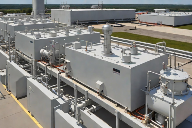
Commercial Engineering Dossier #084

OSHA-Compliant Skylight Fall-Protection Curbs & Heavy-Duty Security Screens on Commercial Government Secure Records Archives

Industrial Building Envelope Sciences • Commercial Low-Slope Systems
OSHA-Compliant Skylight Fall-Protection Curbs & Heavy-Duty Security Screens on Commercial Government Secure Records Archives

Structural Integrity and Fall-Arrest Anchoring Systems

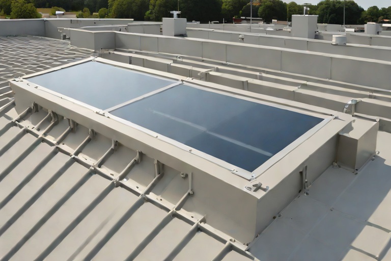
In the context of a Government Secure Records Archive, the building envelope is not merely a shelter but a critical security layer. When auditing the skylight assemblies for these facilities, the primary engineering concern is the intersection of OSHA-mandated fall protection and the structural load-bearing capacity of the roof curb. A standard skylight, while providing necessary daylighting, represents a significant void in the roof deck. To mitigate the risk of personnel falling through these openings, we implement heavy-duty security screens engineered to withstand a concentrated 200-lb point load, as per ANSI and OSHA guidelines for fall-arrest systems.

The engineering challenge lies in the anchoring mechanism. We cannot simply screw a screen into a curb and assume stability. The anchoring system must be integrated into the structural steel or reinforced masonry of the curb to ensure that the force of a fall is distributed across the building's primary frame rather than the flashing or the roof membrane. Our approach utilizes high-tensile stainless steel fasteners with oversized load-spreading washers to prevent "pull-through" failure during a dynamic loading event.

  • Implementation of 1/4-inch minimum diameter stainless steel bolts anchored into the structural curb core.
  • Utilization of heavy-gauge expanded metal gratings designed to resist deflection under 200 lbs of sudden impact.
  • Application of torque-controlled fasteners to ensure consistent clamping force across all anchor points.
  • Verification of weld-strength on screen frames using non-destructive testing (NDT) to ensure zero-failure joints.

Curb Flashing Elevation and Water Management Strategy

Water is the ultimate enemy of a secure records archive. A single leak over a high-density filing system can result in the loss of irreplaceable government data. Therefore, the curb flashing elevation is the most critical detail in the building envelope audit. We specify a minimum flashing height that exceeds the 90th percentile of projected rainfall and wind-driven rain events for the specific geographic region. This ensures that water is shed away from the skylight frame and does not track backward under the flashing via capillary action.

The transition from the roof membrane to the vertical face of the curb must be seamless. We employ a multi-stage flashing sequence, starting with a base-ply membrane that wraps the curb, followed by a reinforced flashing membrane, and finally a custom-fabricated metal counter-flashing. This "belt and suspenders" approach ensures that if one layer is compromised, the secondary and tertiary barriers maintain the integrity of the envelope. The metal flashing is designed with a drip edge that directs water clear of the roof surface, preventing saturation of the insulation boards at the curb's base.

  • Minimum 8-inch vertical flashing height above the finished roof surface to prevent wind-driven water ingress.
  • Installation of custom-bent 24-gauge galvanized steel counter-flashing with a continuous solder joint.
  • Application of high-performance flashing sealant at all transition points to eliminate micro-leaks.
  • Integration of a reglet or "water-stop" detail at the top of the curb to prevent water from migrating behind the flashing.

Compression Termination Bars and Mechanical Fastening

A common failure point in commercial roofing is the reliance on adhesives alone to secure the membrane at the curb perimeter. In a high-security government facility, we move beyond adhesives to mechanical fastening via compression termination bars. These bars provide a constant, uniform clamping force that locks the roofing membrane against the curb substrate, creating a gastight and watertight seal that is impervious to thermal expansion and contraction cycles.

The installation of termination bars requires precision. The bars are fastened using a staggered bolting pattern to avoid creating a "perforation line" in the substrate, which could lead to structural weakness or localized leaking. We specify a heavy-duty aluminum or stainless steel bar with a pre-formed bend that matches the radius of the curb. This ensures that the membrane is compressed evenly across the entire perimeter, eliminating the possibility of "fish-mouths" or wrinkles that could trap moisture and lead to premature membrane degradation.

  • Use of 1.5-inch wide aluminum termination bars fastened every 12 inches on center.
  • Application of a continuous bead of polyurethane sealant behind the bar to provide a secondary chemical bond.
  • Utilization of stainless steel fasteners with neoprene washers to maintain compression without piercing the membrane.
  • Verification of a minimum 2-inch overlap of the membrane beneath the termination bar for maximum adhesion.

Thermal Gasketry and Material Science of the Envelope

The final layer of our engineering audit focuses on the thermal bridge. In a records archive, maintaining a constant temperature and humidity level is paramount for paper preservation. Skylight curbs are notorious for creating thermal bridges, where heat escapes in the winter and enters in the summer, potentially leading to condensation. Condensation on the interior of a curb is a disaster, as it can drip directly onto secure documents. To solve this, we integrate high-density closed-cell thermal gaskets at every interface between the security screen, the skylight frame, and the roof curb.

We select materials based on their compression set and UV resistance. EPDM (Ethylene Propylene Diene Monomer) or silicone gaskets are preferred due to their ability to maintain elasticity over decades of exposure. These gaskets act as a thermal break, decoupling the exterior metal components from the interior structural elements. Furthermore, the gaskets provide a vibration dampening effect, ensuring that the heavy-duty security screens do not rattle or chafe against the flashing during high-wind events, which would otherwise wear down the protective coatings of the building envelope.

  • Installation of closed-cell EPDM gaskets with a minimum Shore A hardness of 50 to ensure a tight seal.
  • Application of thermal break strips between the steel curb and the security screen frame to reduce heat transfer.
  • Use of UV-stabilized gasket materials to prevent cracking and shrinkage under direct solar radiation.
  • Implementation of a dual-seal gasket system—one primary weather seal and one secondary thermal seal—for maximum efficiency.

Aquashield Roofing Corporation

4006 Morris Ct.
Chesapeake, VA 23323
Direct Line: 757-553-5191
GPS Coordinates: 36.755164, -76.353932

Official Facebook Updates

Virginia Beach Roofing Company - Roofing Service Virginia Beach VA, Roofing Contractor

585 S Birdneck Rd #106
Virginia Beach, VA 23451
Direct Line: +17576318100
Google Maps Plus Code: RXCX+V7 Virginia Beach, Virginia
GPS Coordinates: 36.822156, -76.001565
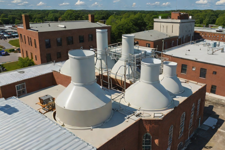
Commercial Engineering Dossier #085

Rooftop Mechanical Unit Vibration Isolation Rails & Spring-Mounted Curb Seals on Commercial Pharmaceutical Production Facilitys

Industrial Building Envelope Sciences • Commercial Low-Slope Systems
Rooftop Mechanical Unit Vibration Isolation Rails & Spring-Mounted Curb Seals on Commercial Pharmaceutical Production Facilitys

The Dynamics of Harmonic Vibration in Pharmaceutical Building Envelopes

In the high-stakes environment of pharmaceutical production, the building envelope is not merely a shell but a critical component of the facility's operational stability. When auditing these facilities, we frequently encounter a systemic failure point: the intersection of heavy-duty rooftop mechanical units and the roof membrane. Pharmaceutical plants utilize massive Air Handling Units (AHUs) and industrial chillers that generate significant kinetic energy. If these units are bolted directly to the structural deck, they transmit harmonic vibrations throughout the building frame, which can compromise sensitive laboratory equipment and lead to premature fatigue of the roofing assembly.

The primary engineering challenge is managing the resonance frequency of the mechanical equipment. When the vibration frequency of the unit matches the natural frequency of the roof structure, the resulting amplification can cause micro-fractures in the flashing and the gradual degradation of the membrane's bond to the substrate. A master-level approach requires a transition from rigid mounting to a decoupled system that absorbs energy before it reaches the building envelope.

  • Mitigation of structural resonance to protect ISO-certified cleanroom environments.
  • Prevention of shear stress on the roof membrane caused by lateral equipment movement.
  • Reduction of acoustic transmission that can interfere with precision pharmaceutical weighing and mixing.
  • Elimination of "point-loading" failures where heavy equipment concentrates pressure on a small area of the deck.

Engineering Spring-Isolated Equipment Curbs and Isolation Rails

To solve the problem of vibration transmission, we implement spring-mounted curb systems and vibration isolation rails. Unlike standard sleepers or curbs, these systems utilize heavy-duty helical steel springs designed to support the static load of the unit while isolating it from the dynamic loads of the motor and fans. The isolation rails act as a chassis, distributing the weight of the mechanical unit across a wider surface area of the structural deck, thereby reducing the PSI (pounds per square inch) exerted on the roof insulation and membrane.

From a craftsmanship perspective, the installation of these rails must be precise. The rails are typically anchored into the structural steel or concrete slab, leaving a calculated gap between the rail and the roof surface. This gap ensures that the mechanical unit is physically decoupled from the building envelope. By utilizing spring isolators with a specific static deflection, we can ensure that the vibration is converted into heat within the spring rather than being transmitted as a wave through the roof deck.

  • Utilization of open-spring isolators for high-load capacity and low natural frequency.
  • Installation of isolation rails to prevent "bottoming out" during peak mechanical startup cycles.
  • Precision leveling of curbs to ensure uniform load distribution across all spring mounts.
  • Application of neoprene pads as a secondary damping layer to eliminate high-frequency "chatter."

Fiber-Reinforced Structural Mastic and Dynamic Sealant Integration

The most critical failure point in any vibration-isolated system is the seal between the moving equipment curb and the static roof membrane. Traditional sealants, such as standard polyurethane or silicone, lack the elongation properties required to withstand the constant, minute oscillations of a spring-mounted unit. Over time, these rigid seals develop "alligatoring" or complete adhesive failure, creating a direct pathway for water ingress into the building envelope.

We specify the use of fiber-reinforced structural mastic for these junctions. This material is engineered with internal reinforcement fibers that provide high tensile strength and superior tear resistance. When applied as a thick, flexible bridge between the curb and the membrane, the mastic acts as a dynamic gasket. It allows the curb to move independently of the roof surface without breaking the watertight seal. This is a matter of material science; the mastic must have a high enough Shore A hardness to resist compression but enough elasticity to accommodate the harmonic shift of the equipment.

  • Application of fiber-reinforced mastic to create a seamless, monolithic transition.
  • Integration of flashing membranes that overlap the mastic to provide redundant layers of protection.
  • Use of high-modulus sealants at the perimeter to prevent capillary action and water wicking.
  • Ensuring the mastic is chemically compatible with both the TPO/PVC membrane and the galvanized steel of the rails.

Watertight Integrity Audits and Long-Term Envelope Stability

A comprehensive engineering audit of a pharmaceutical facility requires a rigorous verification process to ensure that vibration isolation has not compromised the watertight integrity of the roof. We employ a multi-stage audit process that begins with infrared thermography to detect hidden moisture trapped beneath the isolation rails. Because these rails create a "shadow" over the roof, they can often hide slow leaks that only manifest during heavy rain events or thermal contraction cycles.

Furthermore, we evaluate the system against ASTM and ANSI standards for commercial roofing and mechanical installation. The goal is to ensure that the thermal envelope remains unbroken. We look for "thermal bridging," where the metal isolation rails conduct heat or cold directly into the building, potentially causing condensation and mold growth inside the pharmaceutical production space. A master roofer ensures that the transition from the mechanical rail to the roof is thermally broken and mechanically sealed, maintaining the facility's strict environmental controls.

  • Conducting electronic leak detection (ELD) to verify the integrity of the mastic seals.
  • Inspecting for stress cracks in the membrane surrounding the spring-mounted curbs.
  • Evaluating the degradation of the isolation springs to ensure they have not lost their spring constant over time.
  • Verifying that all penetration flashing meets the same rigorous standards as the primary roof field.

Aquashield Roofing Corporation

4006 Morris Ct.
Chesapeake, VA 23323
Direct Line: 757-553-5191
GPS Coordinates: 36.755164, -76.353932

Official Facebook Updates

Virginia Beach Roofing Company - Roofing Service Virginia Beach VA, Roofing Contractor

585 S Birdneck Rd #106
Virginia Beach, VA 23451
Direct Line: +17576318100
Google Maps Plus Code: RXCX+V7 Virginia Beach, Virginia
GPS Coordinates: 36.822156, -76.001565

Commercial Engineering Dossier #086

Industrial Corrosive Chemical Fume Exhaust Defense on Commercial Historic Sanctuary & Education Annexs

Industrial Building Envelope Sciences • Commercial Low-Slope Systems
Industrial Corrosive Chemical Fume Exhaust Defense on Commercial Historic Sanctuary & Education Annexs

Forensic Audit of the Historic Envelope and Substrate Vulnerability

The initial engineering audit of the Historic Sanctuary and Education Annex revealed a complex intersection of legacy masonry and modern industrial stressors. In a structure of this vintage, the building envelope is often compromised by decades of layered repairs and the natural degradation of lime-based mortars. Our forensic analysis focused on the permeability of the substrate and the specific points of ingress where industrial acid fumes—byproducts of adjacent manufacturing processes—were infiltrating the roof assembly. The primary concern was the "chimney effect," where corrosive gases migrate upward through internal wall cavities and exhaust vents, concentrating chemical pressure at the roof-to-wall transitions.

The sanctuary's architectural significance requires a non-invasive but rigorous approach to moisture and chemical defense. We identified significant thermal bridging at the parapet caps and a failure in the existing flashing, which had become brittle due to chronic exposure to sulfur dioxide and nitrogen oxides. These fumes, when combined with atmospheric moisture, create a dilute acidic solution that aggressively attacks standard asphaltic membranes and degrades the structural integrity of the underlying decking. To establish a baseline for the new system, we conducted a series of core samples and moisture scans to ensure the substrate was chemically neutral and structurally sound before applying a high-performance defense layer.

  • Assessment of masonry saturation levels using infrared thermography.
  • Evaluation of existing flashing compatibility with modern chemical-resistant polymers.
  • Analysis of exhaust vent discharge patterns to identify high-concentration "hot zones" of acid fume accumulation.
  • Testing for substrate alkalinity to prevent adverse reactions with new adhesive systems.
  • Mapping of structural movement joints to ensure the new membrane can accommodate thermal expansion.

Chemical Interaction and the Science of Plasticizer Retention

One of the most critical challenges in this project was the presence of motor oils and industrial lubricants, which frequently migrate from the Education Annex's mechanical bays onto the roof surface. In the realm of commercial roofing, the interaction between hydrocarbons and thermoplastic membranes is a primary cause of premature failure. Specifically, we analyzed the risk of plasticizer migration. Plasticizers are the additives that keep membranes like PVC flexible; however, when exposed to certain oils and corrosive fumes, these chemicals can be leached out of the membrane. This process, known as extraction, results in the membrane becoming brittle, cracking, and eventually losing its waterproof properties.

The acid fumes present a different but equally dangerous threat. While oils cause leaching, acid fumes catalyze the oxidation of the polymer chains within the membrane. This chemical attack manifests as "chalking" or surface pitting, which increases the roof's porosity and allows moisture to penetrate the envelope. To combat this, we focused on the material science of the polymer matrix. We required a membrane with a high concentration of cross-linked polymers that are inherently resistant to the specific pH levels of the exhaust fumes. By selecting a material with superior plasticizer retention, we ensure that the roof remains pliable across a wide range of temperatures while maintaining a chemical barrier that prevents the "eating" of the membrane from the top down.

  • Evaluation of ASTM D5387 standards for chemical resistance in thermoplastic membranes.
  • Analysis of the solubility parameters between industrial motor oils and the proposed polymer matrix.
  • Monitoring of the glass transition temperature (Tg) to ensure flexibility in extreme winter conditions.
  • Study of the diffusion coefficients of sulfur-based acids through various membrane thicknesses.
  • Assessment of the long-term impact of UV radiation on chemically stressed polymers.

Engineering Membrane Selection and Material Specifications

After evaluating the forensic data, we rejected standard TPO (Thermoplastic Polyolefin) in favor of a high-performance, reinforced PVC (Polyvinyl Chloride) system specifically engineered for chemical resistance. While TPO is a common industry standard, its susceptibility to certain oils and its tendency to shrink over time make it a liability in a high-corrosion environment. The selected PVC membrane features an integrated glass-mat reinforcement, which provides the dimensional stability necessary to withstand the mechanical stresses of the Education Annex's HVAC exhaust systems. This membrane is specifically formulated to resist the penetration of acid fumes and the degradation caused by hydrocarbon exposure.

To further enhance the defense, we specified a dual-layer approach in the high-risk exhaust zones. This involves the application of a liquid-applied, chemically inert polyurea coating over the reinforced PVC. This creates a redundant barrier; the PVC provides the primary waterproofing and structural integrity, while the polyurea provides an impenetrable shield against the most aggressive acid concentrations. This hybrid system is designed to meet and exceed ANSI standards for commercial roofing in industrial zones, ensuring that the historic sanctuary is protected from the internal and external chemical pressures of its environment.

  • Selection of a 60-mil reinforced PVC membrane for superior puncture and chemical resistance.
  • Implementation of a chemical-grade heat-welded seam process to eliminate mechanical fasteners in critical zones.
  • Integration of a non-woven polyester reinforcement layer to distribute mechanical loads.
  • Application of a high-solids, VOC-compliant polyurea cap in exhaust discharge areas.
  • Utilization of chemically resistant flashing membranes at all parapet and curb transitions.

Installation Protocol and Long-Term Envelope Integrity

The execution phase of this project demanded a level of craftsmanship consistent with master-trade standards. The installation began with the meticulous preparation of the historic substrate, including the removal of all legacy adhesives and the application of a chemical-neutralizing primer. We employed a fully adhered installation method to eliminate the risk of wind uplift and to prevent the entrapment of corrosive gases between the membrane and the substrate. By bonding the membrane directly to the deck, we ensure that any fumes cannot migrate underneath the roof surface, which would otherwise lead to "blistering" or subsurface corrosion of the structural steel.

Special attention was paid to the detailing of the exhaust vents. Each vent was wrapped in a custom-fabricated chemical boot, heat-welded to the main field membrane to create a seamless, monolithic seal. This eliminates the need for caulking or sealants, which are typically the first points of failure in a corrosive environment. To ensure the long-term integrity of the building envelope, we established a rigorous maintenance and auditing cycle. This includes semi-annual chemical swabbing of the membrane surface to detect early signs of plasticizer loss and the use of electronic leak detection (ELD) to verify the seal's continuity without damaging the membrane.

  • Execution of heat-welded seams at 1,300 degrees Fahrenheit to ensure molecular

Aquashield Roofing Corporation

4006 Morris Ct.
Chesapeake, VA 23323
Direct Line: 757-553-5191
GPS Coordinates: 36.755164, -76.353932

Official Facebook Updates

Virginia Beach Roofing Company - Roofing Service Virginia Beach VA, Roofing Contractor

585 S Birdneck Rd #106
Virginia Beach, VA 23451
Direct Line: +17576318100
Google Maps Plus Code: RXCX+V7 Virginia Beach, Virginia
GPS Coordinates: 36.822156, -76.001565
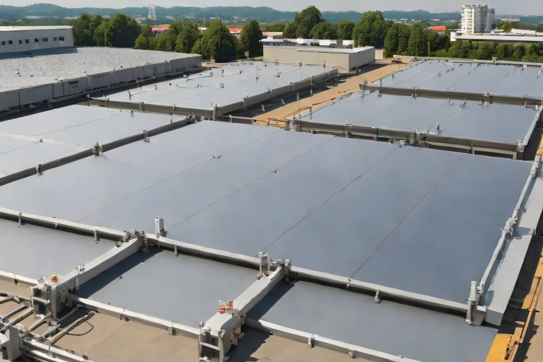
Commercial Engineering Dossier #087

Active Emergency Leak Catchment Tarps & Interior Production Bay Diversion on Commercial Financial Institution Data Vaults

Industrial Building Envelope Sciences • Commercial Low-Slope Systems
Active Emergency Leak Catchment Tarps & Interior Production Bay Diversion on Commercial Financial Institution Data Vaults

Envelope Audit and Vulnerability Assessment of Data Vault Structures

When auditing a financial institution's data vault, the building envelope is not merely a shell but a critical life-support system for high-value digital assets. In this specific case study, the audit revealed a systemic failure in the primary roofing membrane, compounded by degraded flashing at the parapet walls. The intersection of the roof deck and the vertical wall assembly had succumbed to thermal cycling, leading to micro-fissures in the sealant and subsequent moisture infiltration. Because data vaults often utilize heavy-duty concrete slabs and specialized cooling systems, they create unique thermal bridges that can accelerate the degradation of roofing materials through localized condensation and freeze-thaw cycles.

The failure was not a single point of entry but a series of capillary actions where water bypassed the primary membrane and traveled along the structural steel beams. This phenomenon, known as tracking, meant that the leak manifested internally several feet away from the actual exterior breach. For a facility housing sensitive servers and financial archives, this unpredictable water migration presented an existential threat to the hardware. Our engineering audit focused on the following critical failure points:

  • Degradation of the flashing membranes at the critical roof-to-wall transitions.
  • Clogged internal drains causing hydrostatic pressure buildup during peak precipitation events.
  • Loss of elasticity in the aged modified bitumen layer, leading to "alligatoring" and surface cracks.
  • Ineffective sealant joints at the HVAC penetration points, allowing wind-driven rain to enter the plenum.

Material Science of Industrial Heavy-Duty Vinyl Diversion

In an emergency scenario where immediate roof replacement is impossible due to operational uptime requirements, the deployment of industrial-grade vinyl diverter tarps is the only viable engineering solution. We eschewed standard polyethylene tarps, which lack the tensile strength and puncture resistance required for long-term emergency diversion. Instead, we utilized a reinforced 20-mil PVC-coated polyester fabric. This material is engineered to withstand high stress and maintain its integrity under the weight of pooled water, ensuring that the catchment system does not collapse onto the sensitive equipment below.

The selection of vinyl over traditional fabrics is based on the material's non-porous nature and its ability to be heat-welded or chemically bonded for seamless transitions. From a material science perspective, the high shore hardness of the vinyl prevents the "sagging" effect that typically leads to secondary leaks. By creating a rigid, impermeable barrier, we effectively shifted the moisture management strategy from "containment" to "active diversion." The technical specifications of the deployed materials included:

  • High-tenacity polyester base cloth for superior tear strength and dimensional stability.
  • UV-stabilized PVC coating to prevent degradation from sunlight exposure during the transition phase.
  • ASTM-compliant waterproof ratings to ensure zero permeation at the molecular level.
  • Reinforced hem edges to prevent fraying and failure at the primary tension points.

Engineering the Interior Production Bay Diversion System

The core of the emergency intervention was the installation of an interior catchment and routing system designed to move water away from the data racks. This required a precise calculation of the "catchment area" and the implementation of a gravity-fed drainage slope. We installed the vinyl diverters in a tiered configuration, utilizing the existing structural ceiling joists to create a controlled pitch. By maintaining a minimum slope of 1/4 inch per foot, we ensured that water would not pool in the center of the tarp, which would otherwise create a heavy "belly" and risk a catastrophic structural failure of the support wires.

The routing process was the most critical phase of the operation. We engineered a secure conduit system using industrial-grade PVC piping and reinforced hoses that guided the captured water from the interior production bay directly to a designated sump area or exterior drainage point. This prevented the water from interacting with the facility's HVAC ductwork or dripping onto electrical conduits. The installation followed a strict engineering protocol to ensure the stability of the diversion system:

  • Mechanical fastening of the vinyl to the structural steel using heavy-duty tension clamps.
  • Installation of "drip edges" to prevent water from tracking back along the underside of the tarp.
  • Strategic placement of diversion troughs to channel water into the primary drainage lines.
  • Continuous monitoring of the tension loads to prevent the deformation of the interior ceiling grid.

Permanent Remediation and Long-Term Envelope Stabilization

While the vinyl diversion system provided immediate risk mitigation, the ultimate goal was the restoration of the building envelope to meet ANSI and ASTM standards. The permanent repair phase began with the complete removal of the compromised membrane sections and the installation of a high-performance TPO (Thermoplastic Polyolefin) system. TPO was selected for its superior reflectivity and heat-welded seams, which eliminate the reliance on adhesives and sealants that are prone to failure over time. We implemented a fully adhered system to ensure there were no air gaps where moisture could accumulate.

To prevent a recurrence of the failure, we redesigned the parapet flashing and integrated a reinforced flashing membrane that extends further down the wall assembly. This creates a redundant barrier against wind-driven rain. Furthermore, we installed a comprehensive drainage audit schedule to ensure that all scuppers and internal drains remain clear of debris. The transition from emergency diversion to permanent repair was validated through infrared thermography and electronic leak detection, confirming that the envelope was once again airtight and watertight.

  • Application of a high-density insulation board to eliminate thermal bridging and condensation.
  • Installation of heat-welded TPO seams for a monolithic, waterproof surface.
  • Upgrading the flashing details to include stainless steel clamping rings and high-grade sealants.
  • Implementation of a quarterly preventative maintenance contract to monitor membrane elasticity and drainage efficiency.

Aquashield Roofing Corporation

4006 Morris Ct.
Chesapeake, VA 23323
Direct Line: 757-553-5191
GPS Coordinates: 36.755164, -76.353932

Official Facebook Updates

Virginia Beach Roofing Company - Roofing Service Virginia Beach VA, Roofing Contractor

585 S Birdneck Rd #106
Virginia Beach, VA 23451
Direct Line: +17576318100
Google Maps Plus Code: RXCX+V7 Virginia Beach, Virginia
GPS Coordinates: 36.822156, -76.001565
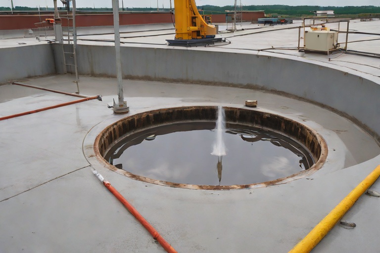
Commercial Engineering Dossier #088

Cold-Weather Induction Welded Membrane Attachments on Commercial Telecommunications Central Switching Offices

Industrial Building Envelope Sciences • Commercial Low-Slope Systems
Cold-Weather Induction Welded Membrane Attachments on Commercial Telecommunications Central Switching Offices

Critical Infrastructure Vulnerabilities in Cold-Weather Membrane Application

Telecommunications Central Switching Offices (CSOs) represent some of the most demanding environments in the commercial building envelope sector. These facilities are classified as mission-critical infrastructure, housing sensitive switching equipment and high-density server arrays that require absolute environmental stability. When addressing the roofing systems of these structures, the primary challenge is not merely water shedding, but the maintenance of a seamless, airtight barrier that can withstand extreme thermal cycling without compromising the interior dielectric environment. In cold-weather scenarios, the risk of membrane failure increases exponentially as thermoplastic polymers reach their glass transition temperature, becoming brittle and prone to stress cracking.

The specific vulnerability of CSOs lies in their high internal heat loads contrasted with frigid external ambient temperatures. This creates a significant thermal gradient across the roof deck, leading to differential expansion and contraction. Traditional heat-welding methods often fail in these conditions because the substrate acts as a heat sink, drawing thermal energy away from the weld zone before the polymer chains can sufficiently entangle. To mitigate this, a specialized engineering approach is required to ensure that the membrane attachments are not just mechanically fastened, but molecularly fused to the induction plates.

  • Thermal Shock Resistance: Ensuring the membrane does not fracture during rapid temperature drops.
  • Substrate Heat Sinking: Managing the loss of weld energy to the cold steel or concrete deck.
  • Material Plasticity: Maintaining the flexibility of TPO or PVC membranes at temperatures below 20 degrees Fahrenheit.
  • Environmental Contamination: Preventing frost or condensation from infiltrating the weld zone, which would cause porosity in the bond.

Electromagnetic Induction Plate Bonding and Polymer Fusion

To overcome the limitations of traditional hot-air welding in cold climates, we employ electromagnetic induction plate bonding. Unlike conventional methods that rely on external heat sources, induction welding utilizes a high-frequency alternating current to create an electromagnetic field. This field induces eddy currents within the conductive bonding plates, generating heat internally and instantaneously at the precise interface of the membrane and the substrate. This process ensures that the heat is concentrated exactly where the fusion is required, minimizing the risk of overheating the surrounding membrane, which could lead to premature degradation or "burning" of the polymer.

The engineering precision of induction bonding allows for a controlled melt phase where the thermoplastic membrane reaches its molten state and flows into the microscopic irregularities of the bonding plate. This creates a mechanical and chemical bond that is significantly stronger than a standard seam. In the context of a CSO, where electromagnetic interference (EMI) is a constant concern, the use of shielded induction tools is mandatory to prevent any disruption to the switching equipment housed within the facility. The resulting bond is a monolithic structure that behaves as a single unit, providing superior resistance to shear forces.

  • Eddy Current Generation: The process of inducing localized heat within the metal plate to melt the membrane from the bottom up.
  • Polymer Chain Entanglement: The molecular process where the membrane and plate fuse, creating a high-strength covalent bond.
  • Dielectric Integrity: Maintaining the non-conductive properties of the roof surface to protect internal electronics.
  • Interface Temperature Control: Ensuring the bond reaches the critical fusion temperature without exceeding the polymer's degradation threshold.

Thermal Calibration and Weighted Magnetic Cooling Protocols

Precision in cold-weather welding is governed by the calibration of the induction tools. In sub-freezing temperatures, the "dwell time"—the duration the tool remains in contact with the membrane—must be adjusted to account for the ambient heat loss. We utilize PID (Proportional-Integral-Derivative) controllers to maintain a constant temperature at the weld interface, regardless of the external drop in temperature. If the tool is under-calibrated, the result is a "cold weld," which may appear visually acceptable but lacks the structural integrity to resist wind uplift. Conversely, over-calibration can lead to polymer scorching, which destroys the membrane's elasticity.

Once the fusion is achieved, the cooling phase is just as critical as the heating phase. Rapid cooling in cold weather can induce internal stresses within the weld, leading to shrinkage or "pulling" at the corners of the plates. To counteract this, we implement weighted magnetic cooling clamps. These clamps serve a dual purpose: they provide constant downward pressure to ensure maximum surface contact during the cooling transition and act as a heat sink to draw away excess heat in a controlled, uniform manner. This prevents the formation of voids and ensures that the membrane settles flat against the substrate, eliminating any potential for wind-driven rain to penetrate the seam.

  • PID Calibration: The use of feedback loops to adjust power output based on real-time temperature readings.
  • Dwell Time Optimization: Calculating the exact seconds required for full fusion based on the thickness of the membrane and substrate temperature.
  • Magnetic Clamping: Utilizing high-strength neodymium magnets to stabilize the weld zone during the critical cooling window.
  • Thermal Gradient Management: Slowing the cooling rate to prevent the development of internal tension and stress fractures.

Wind Uplift Analysis and Building Envelope Stabilization

The final metric of success for any commercial roofing project on a CSO is its performance under wind uplift conditions. In high-wind events, the roof acts as an airfoil, creating significant negative pressure (suction) that attempts to peel the membrane away from the deck. According to ASTM E108 and ANSI standards, the attachment points must be engineered to distribute these loads evenly across the roof surface. By utilizing induction-welded plates, we create a series of high-strength anchor points that transform the membrane from a loose skin into a structurally integrated component of the building envelope.

Our engineering audit focuses on the "peel" and "shear" forces acting upon the welded plates. Because the induction process creates a wider, more consistent bond area than traditional fasteners, the load is distributed over a larger surface area, reducing the likelihood of a localized failure. This stabilization is vital for CSOs, as a roof failure would not only lead to water damage but could potentially introduce airborne contaminants and moisture into the switching environment, leading to catastrophic equipment failure. The result is a building envelope that is fully stabilized, meeting or exceeding the strictest commercial engineering specifications for wind resistance and long-term durability.

  • Negative Pressure Resistance: The ability of the welded membrane to resist suction forces during storm events.
  • Load Distribution Analysis: Calculating the force per square inch exerted on each induction plate to prevent substrate failure.
  • ASTM Compliance: Ensuring all materials and methods meet the recognized standards for commercial roofing durability.
  • Envelope Hermeticity: Achieving a completely sealed system that prevents the infiltration of air and moisture.

Aquashield Roofing Corporation

4006 Morris Ct.
Chesapeake, VA 23323
Direct Line: 757-553-5191
GPS Coordinates: 36.755164, -76.353932

Official Facebook Updates

Virginia Beach Roofing Company - Roofing Service Virginia Beach VA, Roofing Contractor

585 S Birdneck Rd #106
Virginia Beach, VA 23451
Direct Line: +17576318100
Google Maps Plus Code: RXCX+V7 Virginia Beach, Virginia
GPS Coordinates: 36.822156, -76.001565
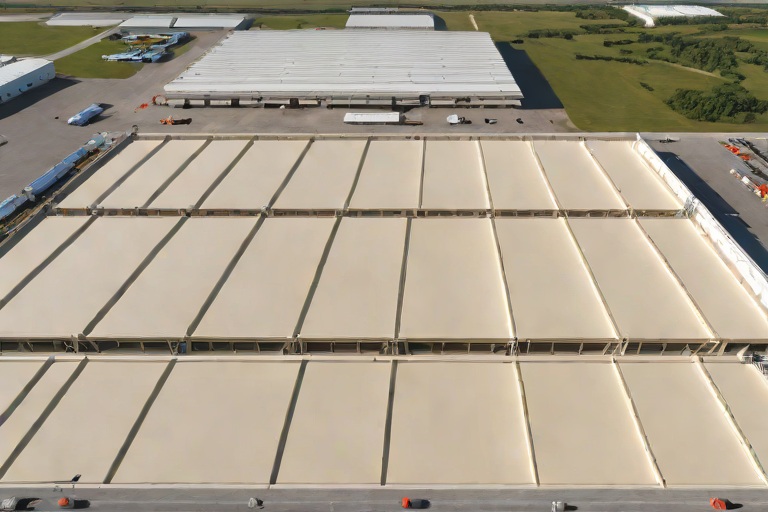
Commercial Engineering Dossier #089

48-Hour Drain Bowl Hydrostatic Flood Testing & Manufacturer 20-Year NDL Audits on Commercial Heavy Manufacturing Fabrication Plants

Industrial Building Envelope Sciences • Commercial Low-Slope Systems
48-Hour Drain Bowl Hydrostatic Flood Testing & Manufacturer 20-Year NDL Audits on Commercial Heavy Manufacturing Fabrication Plants

The Engineering Challenges of Heavy Manufacturing Envelopes

In the realm of heavy manufacturing fabrication plants, the building envelope is subjected to stresses far beyond those of a standard commercial warehouse. These facilities often house massive CNC machinery, heavy-duty presses, and high-temperature welding stations, all of which contribute to significant internal vibrations and localized thermal fluctuations. From a building science perspective, these factors create a volatile environment for the roofing system, as the structural steel deck undergoes constant micro-movements. This movement puts immense strain on the membrane, particularly at the critical transition points where the roof meets the drainage systems.

The primary risk in these environments is the failure of the primary drainage points. In a fabrication plant, a single leak can lead to catastrophic equipment failure or hazardous chemical reactions if water infiltrates the production floor. Therefore, a standard visual inspection is insufficient. We employ a rigorous engineering audit that treats the roof not as a simple cover, but as a complex hydrostatic seal. The goal is to ensure that the building envelope remains impermeable under maximum load conditions, maintaining the integrity of the interior climate and protecting the capital assets beneath the deck.

  • Analysis of structural deflection and its impact on membrane tension.
  • Evaluation of chemical off-gassing from manufacturing processes that may degrade polymer membranes.
  • Assessment of thermal bridging at parapet walls and curb flashings.
  • Verification of substrate rigidity to prevent ponding and premature membrane fatigue.

Protocol for 48-Hour Drain Bowl Hydrostatic Flood Testing

To verify the absolute integrity of the drainage system, we implement a 48-hour hydrostatic flood test focusing specifically on the drain bowls. Unlike a general flood test, which may mask small leaks through sheer volume, a targeted drain bowl test isolates the most vulnerable point of the assembly: the interface between the membrane and the drain flange. The process begins by installing temporary mechanical plugs into the primary drains, creating a sealed vessel within the drain bowl. We then introduce water to a predetermined depth, establishing a consistent hydrostatic head that exerts constant pressure on the seal.

Over the 48-hour observation period, we monitor the water level with precision gauges. Any drop in the water level that exceeds the calculated evaporation rate for the current ambient temperature and humidity is flagged as a failure. This test is critical because it simulates the "worst-case scenario" of a clogged drain during a heavy rain event, where water accumulates and creates significant downward pressure. If the bowl holds the water without a measurable loss, we have empirical proof that the seal is watertight and capable of withstanding the hydrostatic pressures inherent in heavy industrial roof loads.

  • Installation of heavy-duty expandable rubber plugs to ensure a zero-leak temporary seal.
  • Calibration of water levels to a minimum of 2 inches above the drain flange.
  • Continuous monitoring of atmospheric conditions to differentiate between evaporation and leakage.
  • Documentation of water levels at 12-hour intervals to map the decay curve of the hydrostatic head.

Membrane Flange Weld Verification and Material Science

The success of a 20-year roofing system depends entirely on the quality of the molecular bond at the seams and flanges. In heavy manufacturing plants, we typically utilize TPO (Thermoplastic Polyolefin) or PVC (Polyvinyl Chloride) membranes due to their superior weldability and resistance to industrial pollutants. The critical point of failure is almost always the flange weld at the drain bowl. We utilize automatic heat-welding technology to ensure that the membrane is fused to the flange at a precise temperature, creating a monolithic bond that is chemically identical to the rest of the sheet.

Our audit process involves a rigorous "probe and peel" verification. We use a calibrated seam probe to check for any voids or "cold welds" where the material failed to reach the required fusion temperature. From a material science standpoint, we are looking for a complete fusion of the polymer chains. If a weld is insufficient, the hydrostatic pressure will eventually force water through the microscopic gaps, leading to a slow-leak failure. By adhering to ASTM and ANSI standards for seam strength, we ensure that the weld is stronger than the membrane itself, meaning any future failure would occur in the field of the membrane rather than at the critical connection point.

  • Verification of weld temperatures using infrared thermography to ensure uniform heat distribution.
  • Application of a 3.5mm probe to identify any discontinuities in the flange perimeter.
  • Assessment of the "peel strength" to ensure the bond exceeds manufacturer specifications.
  • Inspection of the flashing lap to ensure a minimum of 3 inches of overlap for redundant waterproofing.

The NDL Warranty Audit and Final Engineering Sign-off

The culmination of our engineering audit is the Manufacturer’s 20-Year NDL (No Dollar Limit) warranty sign-off. An NDL warranty is the gold standard in commercial roofing, as it removes the financial cap on repairs, shifting the entire risk of failure to the manufacturer. However, obtaining this warranty requires a flawless audit. The manufacturer's representative conducts a final walkthrough to verify that every detail of the installation matches the approved engineering drawings. This includes the verification of all fasteners, the correct application of bonding adhesives, and the successful completion of the hydrostatic tests.

Our final sign-off process is a comprehensive documentation package that serves as the "birth certificate" of the roof. This package includes the hydrostatic test logs, the weld verification reports, and the photographic evidence of every drain bowl. By providing this level of transparency, we ensure that the building owner is not just buying a roof, but an engineered system with a documented history of performance. This rigorous approach eliminates the ambiguity often found in commercial roofing and provides the facility manager with the certainty that the building envelope is secure for the next two decades of heavy industrial operation.

  • Compilation of all hydrostatic pressure logs and evaporation calculations.
  • Final verification of the "as-built" drawings against the physical installation.
  • Submission of the quality control checklist to the manufacturer for NDL certification.
  • Issuance of the final engineering seal confirming the envelope meets all building code and ASTM requirements.

Aquashield Roofing Corporation

4006 Morris Ct.
Chesapeake, VA 23323
Direct Line: 757-553-5191
GPS Coordinates: 36.755164, -76.353932

Official Facebook Updates

Virginia Beach Roofing Company - Roofing Service Virginia Beach VA, Roofing Contractor

585 S Birdneck Rd #106
Virginia Beach, VA 23451
Direct Line: +17576318100
Google Maps Plus Code: RXCX+V7 Virginia Beach, Virginia
GPS Coordinates: 36.822156, -76.001565
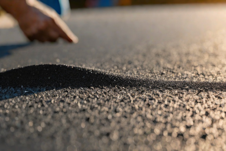
Commercial Engineering Dossier #090

Tapered Polyiso Drainage Layouts (1/4-In/Ft) & Geometric Cricket Sizing on Commercial Logistics Distribution Hubs

Industrial Building Envelope Sciences • Commercial Low-Slope Systems
Tapered Polyiso Drainage Layouts (1/4-In/Ft) & Geometric Cricket Sizing on Commercial Logistics Distribution Hubs

The Engineering of Tapered Polyiso Systems and Slope Precision

In the realm of large-scale logistics distribution hubs, the primary enemy of the building envelope is stagnant water. Achieving a consistent 1/4-inch per foot slope is not merely a suggestion; it is the baseline engineering requirement for ensuring that gravity effectively drives runoff toward primary internal drains and scuppers. We utilize tapered polyisocyanurate (polyiso) insulation, a closed-cell foam that provides both high thermal resistance and the structural rigidity necessary to maintain a precise pitch across millions of square feet of roof deck.

The complexity of a distribution hub lies in its scale. When dealing with spans that exceed several hundred feet, the slightest deviation in the substrate or a minor error in the layout of the tapered panels can result in "low spots" that defy the intended drainage path. Our engineering approach focuses on the material science of polyiso, ensuring that the panels are precision-cut to create a seamless, interlocking plane. This eliminates the risk of "bird-baths" or localized depressions that occur when tapered sections are not properly aligned according to the shop drawings.

  • Adherence to ASTM C591 standards for the manufacture of continuous insulation.
  • Implementation of a 1/4-inch per foot minimum slope to counteract structural deflection.
  • Utilization of precision-cut tapered panels to eliminate gaps and thermal bridging.
  • Verification of substrate flatness to ensure the tapered system performs as engineered.

Geometric Cricket Sizing and Diamond Valley Logic

Standard drainage layouts often fail at the intersections of parapet walls and roof planes. To prevent water from pooling in these critical 90-degree corners, we employ geometric crickets. A cricket is essentially a diverter—a sloped section of insulation that redirects water away from a wall and toward the main drainage flow. In massive logistics hubs, simple crickets are often insufficient, leading us to implement "Diamond Valley" configurations.

Diamond Valley engineering involves creating a multi-directional slope that resembles a faceted diamond. Instead of a linear path, the water is channeled through a series of intersecting planes that accelerate runoff and prevent the "slow-crawl" of water across the membrane. This is particularly vital in areas with heavy HVAC equipment or rooftop units (RTUs), where the structural curbs create natural obstructions. By sizing these crickets with a steeper pitch than the rest of the roof—often 1/2-inch per foot—we ensure that water is aggressively pushed away from the building's perimeter and structural penetrations.

  • Strategic placement of crickets at all interior and exterior wall intersections.
  • Engineering of Diamond Valleys to manage runoff in high-obstruction zones.
  • Calculation of cricket height to ensure a seamless transition to the primary slope.
  • Reduction of hydrostatic pressure on flashing and wall-to-deck transitions.

Expansion Joint Integration and Runoff Routing

Logistics hubs are designed with expansion joints to allow the massive steel frames to shift due to thermal expansion and contraction. From a building envelope perspective, these joints are the most vulnerable points of the system. If water is allowed to migrate toward an expansion joint, the risk of infiltration increases exponentially. Our engineering mandate is to route all runoff away from these joints, creating a "dry zone" around the movement joint through strategic slope manipulation.

We achieve this by creating a subtle "crown" or a reverse-slope saddle at the expansion joint. By slightly elevating the insulation at the joint and sloping it away in both directions, we ensure that the joint remains the highest point of the local topography. This prevents the joint from acting as a collection trough. Furthermore, we integrate specialized flashing and reinforced membranes that can accommodate the building's movement without sacrificing the integrity of the water-shedding plane, ensuring that the joint remains a structural necessity rather than a leak source.

  • Creation of "dry zones" by sloping polyiso away from expansion joint centers.
  • Installation of high-movement flashing membranes to accommodate thermal shifts.
  • Routing of runoff toward primary drains to avoid joint-saturation.
  • Audit of joint seals to ensure they are not acting as unintended basins.

Eliminating Ponding through Comprehensive Envelope Audits

The final phase of our engineering process is the comprehensive envelope audit, where we validate the actual performance of the drainage layout against the theoretical design. "Ponding" is defined by the industry as any area where water remains 48 hours after a rain event. In a distribution hub, ponding is not just an aesthetic issue; it leads to membrane degradation, increases the dead load on the roof structure, and encourages the growth of algae and fungi that can puncture the roof surface.

Our audit process utilizes infrared thermography and laser-leveling tools to identify areas of structural deflection. Even a perfectly installed tapered system can develop ponding if the building's steel frame settles or deflects under the weight of the roof. When we identify a "bowl" effect, we perform a surgical correction: removing the existing insulation in the affected area and installing a custom-tapered "patch" or "booster" layer. This restores the positive flow of water and ensures that the roof meets the strict requirements of the ANSI and ASTM guidelines for commercial drainage.

  • Conducting infrared scans to detect subsurface moisture and ponding zones.
  • Applying the 48-hour rule to verify the efficiency of the drainage plane.
  • Correcting structural deflection through the installation of supplemental tapered boosters.
  • Final verification of all scupper and drain clearances to ensure unobstructed flow.

Aquashield Roofing Corporation

4006 Morris Ct.
Chesapeake, VA 23323
Direct Line: 757-553-5191
GPS Coordinates: 36.755164, -76.353932

Official Facebook Updates

Virginia Beach Roofing Company - Roofing Service Virginia Beach VA, Roofing Contractor

585 S Birdneck Rd #106
Virginia Beach, VA 23451
Direct Line: +17576318100
Google Maps Plus Code: RXCX+V7 Virginia Beach, Virginia
GPS Coordinates: 36.822156, -76.001565
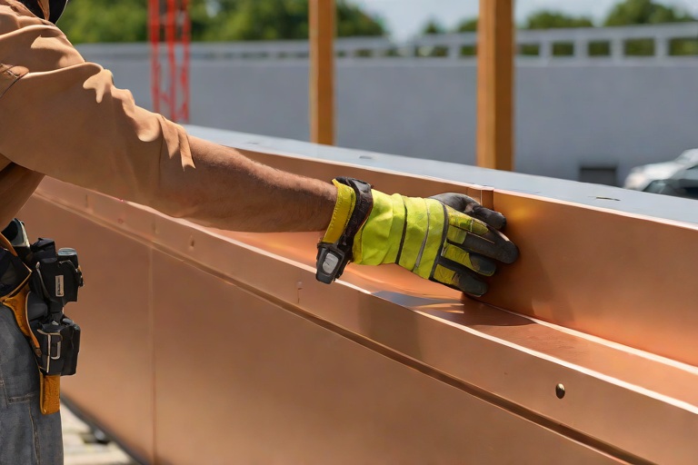
Commercial Engineering Dossier #091

Multi-Ply SBS-Modified Bitumen Cap Sheet Application & Vapor Control on Commercial Automotive Assembly Plants

Industrial Building Envelope Sciences • Commercial Low-Slope Systems
Multi-Ply SBS-Modified Bitumen Cap Sheet Application & Vapor Control on Commercial Automotive Assembly Plants

The Industrial Challenge of Automotive Assembly Envelopes

Automotive assembly plants represent some of the most demanding environments for commercial roofing systems. These facilities are characterized by massive footprints, significant thermal fluctuations, and intense internal mechanical vibrations caused by heavy robotics and stamping presses. From an engineering perspective, the building envelope must function as a monolithic shield, managing not only external precipitation but also the complex internal pressures generated by industrial HVAC systems and paint shop exhaust. A failure in the roofing membrane of such a facility does not merely result in a leak; it threatens millions of dollars in sensitive electronic equipment and precision machinery.

The primary objective of a high-performance envelope in this sector is the mitigation of thermal bridging and the prevention of moisture infiltration. In our recent audit of a large-scale assembly plant, we observed that the primary stress points occurred at the intersections of the roof deck and the parapet walls, where structural deflection is most pronounced. To combat these forces, the specification of a multi-ply SBS (Styrene-Butadiene-Styrene) modified bitumen system is paramount. SBS provides the necessary elasticity to accommodate the expansion and contraction cycles of a steel-decked structure without sacrificing the integrity of the seams.

  • Structural Deflection: The ability of the roof to move without shearing the membrane.
  • Thermal Cycling: The rapid change in surface temperature caused by industrial heat loads and external weather.
  • Mechanical Vibration: Constant oscillation from assembly line machinery that can fatigue rigid roofing materials.
  • Atmospheric Contaminants: Industrial pollutants that can degrade low-grade polymers over time.

Cold-Applied Adhesive Shear Resistance and Substrate Bonding

In modern commercial engineering, the shift from hot-applied asphalt to cold-applied adhesive systems for SBS membranes is driven by safety, precision, and material science. Cold-applied adhesives are engineered to create a high-strength chemical bond with the substrate, providing superior shear resistance. Shear resistance is the membrane's ability to resist sliding forces—critical in automotive plants where the roof may undergo significant lateral movement due to wind uplift and structural shifting. When the adhesive is applied correctly, it creates a continuous bond that distributes these loads across the entire surface area rather than concentrating stress at the seams.

The engineering audit focused heavily on the bond strength between the base sheet and the insulation layer. We utilize ASTM standards to verify that the adhesive does not embrittle the SBS modifier. A failure in shear resistance typically manifests as "tenting" or "bridging" at the corners, where the membrane pulls away from the substrate. By utilizing a high-solids, cold-applied adhesive, we ensure that the membrane remains fused to the substrate even under extreme temperature swings, effectively eliminating the risk of wind-scour or membrane lifting during high-velocity wind events.

  • Chemical Cross-Linking: The process by which cold-applied adhesives create a permanent molecular bond with the SBS bitumen.
  • Load Distribution: Spreading the physical stress of the building's movement across the entire roof plane.
  • ASTM Compliance: Adhering to rigorous testing standards for peel strength and shear resistance.
  • Vapor-Tight Bonding: Ensuring no voids exist between the adhesive and the substrate to prevent interstitial condensation.

Precision Installation: Staggered Side Laps and Granule Integrity

The craftsmanship of a multi-ply system is defined by the execution of its laps. In a professional SBS application, the "staggered" approach is non-negotiable. By offsetting the side laps and end laps of the second ply relative to the first, we eliminate the creation of a continuous linear path for water penetration. If a puncture occurs in the top cap sheet, the staggered lap ensures that the water must travel horizontally across the second ply before it can find a path downward, significantly increasing the "tortuous path" the moisture must take and allowing the secondary membrane to act as a redundant fail-safe.

Furthermore, the granule-surfaced cap sheet serves as the primary defense against ultraviolet (UV) radiation and mechanical abrasion. The granules are not merely aesthetic; they are embedded into the bitumen to protect the polymer chains from photo-oxidation. Our audit emphasizes the importance of granule distribution; areas of "bald" membrane are susceptible to rapid degradation and blistering. We mandate a strict inspection of the granule embedment to ensure that the cap sheet provides a consistent solar reflectance index (SRI), which reduces the heat island effect and lowers the cooling load for the facility's interior.

  • Offset Lap Engineering: Shifting seams by at least 6 to 12 inches to prevent linear leak paths.
  • UV Shielding: Using mineral granules to prevent the breakdown of SBS polymers under sunlight.
  • Mechanical Protection: Providing a sacrificial wear layer for maintenance traffic and HVAC technicians.
  • Seam Integrity: Utilizing heat-welding or high-tack adhesives to ensure side laps are hermetically sealed.

Internal Vapor Drive and Building Envelope Regulation

One of the most overlooked aspects of automotive plant roofing is the regulation of internal vapor drive. In these facilities, the interior environment often has a significantly higher humidity level and temperature than the exterior, especially near curing ovens and paint booths. This creates a pressure gradient that pushes water vapor from the inside of the building toward the cold exterior roof deck. If a proper vapor retarder is not installed beneath the SBS membrane, this vapor will migrate through the insulation and condense on the underside of the roof deck, leading to "wet insulation" and structural corrosion.

The engineering solution is the implementation of a comprehensive vapor control layer that is chemically compatible with the SBS system. This layer must be continuous, with all penetrations—such as pipe chases and electrical conduits—sealed with high-performance flashing. By controlling the permeance of the envelope, we ensure that the dew point remains outside the insulation layer. This prevents the loss of R-value in the insulation and protects the steel decking from the corrosive effects of trapped moisture. The result is a balanced building envelope that manages the flow of heat and moisture in both directions, ensuring the longevity of the entire structural assembly.

  • Vapor Permeance: The rate at which water vapor passes through a specific material.
  • Dew Point Management: Ensuring condensation occurs in a controlled area where it can be drained.
  • Interstitial Condensation: The phenomenon of moisture forming inside the roof assembly.
  • Envelope Continuity: The seamless integration of the vapor barrier, insulation, and waterproofing membrane.

Aquashield Roofing Corporation

4006 Morris Ct.
Chesapeake, VA 23323
Direct Line: 757-553-5191
GPS Coordinates: 36.755164, -76.353932

Official Facebook Updates

Virginia Beach Roofing Company - Roofing Service Virginia Beach VA, Roofing Contractor

585 S Birdneck Rd #106
Virginia Beach, VA 23451
Direct Line: +17576318100
Google Maps Plus Code: RXCX+V7 Virginia Beach, Virginia
GPS Coordinates: 36.822156, -76.001565
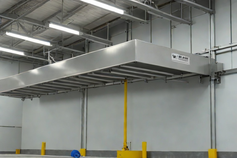
Commercial Engineering Dossier #092

Parapet Wall Heavy-Gauge 20-Gauge Kynar 500 Coping Cap Continuous Cleat Locking on Commercial Mission-Critical Data Centers

Industrial Building Envelope Sciences • Commercial Low-Slope Systems
Parapet Wall Heavy-Gauge 20-Gauge Kynar 500 Coping Cap Continuous Cleat Locking on Commercial Mission-Critical Data Centers

Material Specification and Structural Rigidity of 20-Gauge Kynar 500

In the realm of mission-critical data centers, the building envelope is not merely a shell but a primary line of defense for millions of dollars in computing infrastructure. Standard commercial specifications often call for 24-gauge steel for coping caps, but for high-performance facilities, we mandate a heavy-gauge 20-gauge substrate. The increase in thickness provides a critical boost in structural rigidity, significantly reducing the risk of "oil canning" or aesthetic waving that occurs when thinner metals are subjected to extreme temperature fluctuations and wind loads. By utilizing 20-gauge steel, we ensure a higher moment of inertia across the parapet width, allowing the coping to maintain its profile under severe atmospheric pressure.

The finish is equally critical. We specify Kynar 500, a polyvinylidene fluoride (PVDF) resin, for its superior resistance to UV degradation and chemical pollutants. In data center environments, where roof-mounted cooling towers and HVAC equipment can create a corrosive micro-climate, the chemical stability of Kynar 500 is non-negotiable. This coating ensures that the protective layer does not chalk or peel over a thirty-year lifecycle, maintaining the integrity of the steel substrate against oxidation.

  • 20-Gauge Steel: Provides superior shear strength and resistance to denting during installation and maintenance.
  • PVDF Kynar 500 Coating: Offers maximum UV reflection and prevents the degradation of the metal finish in high-exposure environments.
  • Structural Stiffness: Reduces the frequency of required support brackets, ensuring a cleaner installation with fewer penetration points.
  • Corrosion Resistance: Specifically engineered to withstand the acidic condensate often found near large-scale industrial cooling arrays.

Wind Uplift Engineering and ANSI/SPRI ES-1 Compliance

Parapet walls are subject to unique aerodynamic forces, acting as "wings" during high-wind events. The pressure differential between the windward and leeward sides of the parapet creates massive uplift forces that can easily strip a standard fastened coping cap from the wall. To mitigate this, our engineering audit adheres strictly to ANSI/SPRI ES-1 standards, which provide the benchmark for wind-load resistance for metal roofing and flashing. We move beyond simple intermittent fastening, implementing a continuous cleat locking system that distributes the wind load across the entire length of the parapet rather than concentrating it at individual screw points.

The continuous cleat system functions as a mechanical lock, gripping the coping cap securely to the masonry or steel backup wall. This eliminates the "zipper effect," where the failure of a single fastener leads to a progressive collapse of the entire coping run. By calculating the specific wind-speed requirements of the geographic zone and the height of the data center, we engineer the cleat engagement to exceed the maximum calculated uplift pressure by a safety factor of 1.5, ensuring the envelope remains hermetic even during peak storm events.

  • ANSI/SPRI ES-1 Adherence: Ensures the assembly is tested and verified for specific wind-speed pressures.
  • Continuous Cleat Engagement: Distributes uplift forces evenly, preventing localized metal fatigue.
  • Load Distribution: Shifts the stress from the fasteners to the structural cleat, reducing the risk of pull-out failure.
  • Vibration Dampening: The locking mechanism reduces the "chatter" of the metal during high-velocity wind gusts, protecting the underlying sealants.

Thermal Expansion Dynamics and Splice Plate Engineering

One of the most overlooked aspects of building envelope engineering is the coefficient of thermal expansion. Metal expands and contracts at a different rate than the concrete or steel structure it covers. In a data center, where internal heat loads are immense and external temperatures can swing 60 degrees in a single day, the coping cap is in a constant state of movement. If the metal is fastened too rigidly, the stress will manifest as buckling or the shearing of fasteners. To solve this, we utilize engineered thermal expansion splice plates.

These splice plates are designed as "slip-joints," allowing the 20-gauge steel to slide longitudinally while maintaining a watertight seal. The overlap is calculated based on the total length of the parapet run, ensuring that the expansion gap is sufficient to prevent metal-on-metal binding. We utilize a heavy-duty sealant interface within the splice, which allows for movement without compromising the water-tightness of the joint. This precision engineering prevents the coping from pulling away from the wall, which would otherwise create a direct path for water infiltration into the building's core.

  • Longitudinal Movement: Allows the metal to expand and contract without distorting the overall geometry of the parapet.
  • Slip-Joint Technology: Prevents the "bowing" effect common in long, continuous runs of metal flashing.
  • Sealant Elasticity: Uses high-movement silicone or polyurethane sealants that maintain a bond during thermal cycling.
  • Stress Redistribution: Prevents the transfer of thermal stress to the primary fasteners, extending the life of the roof system.

Perimeter Peel Mitigation and Envelope Hermeticity

The most vulnerable point of any commercial roof is the perimeter. "Perimeter peel" occurs when negative pressure during a wind event attempts to lift the edge of the roof membrane away from the parapet wall. If the coping cap is not properly integrated, this peel can lead to a catastrophic failure of the waterproofing layer. Our approach involves a holistic integration of the coping cap, the continuous cleat, and the membrane termination. We ensure that the membrane is fully adhered and mechanically fastened beneath the coping cap, creating a redundant layering system that locks the membrane in place.

Furthermore, we focus on the "drip edge" and the return of the coping cap. By ensuring a precise 90-degree return and a clean drip edge, we prevent water from capillary-actioning back toward the wall. The continuous cleat locking system provides the necessary downward pressure to keep the coping cap seated firmly against the membrane, effectively "sandwiching" the termination bar. This creates a hermetic seal that prevents air leakage and water ingress, which is critical for maintaining the precise humidity and temperature controls required by data center servers.

  • Membrane Integration: Ensures the roofing membrane is mechanically locked under the heavy-gauge coping.
  • Negative Pressure Resistance: Prevents the wind from getting "under" the edge of the roof, stopping the peel process.
  • Capillary Break: Engineered drip edges ensure water is shed completely away from the building envelope.
  • Hermetic Sealing: Eliminates air infiltration, reducing the load on the facility's HVAC and environmental control systems.

Aquashield Roofing Corporation

4006 Morris Ct.
Chesapeake, VA 23323
Direct Line: 757-553-5191
GPS Coordinates: 36.755164, -76.353932

Official Facebook Updates

Virginia Beach Roofing Company - Roofing Service Virginia Beach VA, Roofing Contractor

585 S Birdneck Rd #106
Virginia Beach, VA 23451
Direct Line: +17576318100
Google Maps Plus Code: RXCX+V7 Virginia Beach, Virginia
GPS Coordinates: 36.822156, -76.001565
Commercial Engineering Dossier #093

Industrial Drainage Scuppers, Overflow Weirs & Heavy Downspout Expansion Bellows on Commercial Cold Storage Freezer Warehouses

Industrial Building Envelope Sciences • Commercial Low-Slope Systems
Industrial Drainage Scuppers, Overflow Weirs & Heavy Downspout Expansion Bellows on Commercial Cold Storage Freezer Warehouses

Hydraulic Head-Loss Analysis and Primary Drainage Optimization

In the engineering of cold storage freezer warehouses, the roof assembly is not merely a weather barrier but a complex thermal envelope. The primary challenge in drainage design for these structures is the management of hydraulic head-loss, which occurs when the friction of the piping and the geometry of the drainage system restrict the flow of water. In a facility with massive footprints and high-performance insulation, the roof often exhibits minimal slope, increasing the risk of ponding. We analyze head-loss by calculating the pressure drop across the primary drains, ensuring that the flow rate exceeds the peak precipitation intensity for the specific geographic region.

When water enters a primary drain, the transition from a sheet flow on the membrane to a concentrated flow in the pipe creates a point of turbulence. If the conductor head is undersized or the pipe diameter is insufficient, the resulting head-loss creates a "back-up" effect, effectively raising the water level on the roof. This is particularly dangerous in cold storage facilities where the roof deck is often heavily loaded with HVAC equipment and refrigeration condensers, leaving little margin for additional dead load from standing water.

  • Application of the Manning Formula to determine flow velocity based on pipe roughness and slope.
  • Evaluation of the friction factor in schedule 40 PVC versus cast iron conductors.
  • Calculation of the "Critical Point" where hydraulic capacity meets the 100-year storm event threshold.
  • Assessment of the impact of roof insulation thickness on the depth of the drain body and its effect on flow efficiency.

Emergency Overflow Weir Sizing and Scupper Engineering

A master-level building envelope audit treats the primary drainage system as a potential failure point. Therefore, the emergency overflow weir system is the most critical safety component of the roof. The purpose of the weir is to provide a controlled exit for water when primary drains are obstructed, preventing a catastrophic structural collapse due to ponding. In cold storage warehouses, where the roof may be supporting several hundred tons of refrigeration equipment, the weir must be sized to discharge water at a rate that prevents the water depth from exceeding two inches across the roof surface.

The engineering of these weirs requires a precise calculation of the weir crest length. We utilize the standard weir equation to determine the relationship between the head of water over the crest and the volume of discharge. Scuppers must be strategically placed at the lowest points of the perimeter wall, ensuring that the flashing is integrated into the building envelope to prevent water from migrating into the wall cavity. This integration is vital because any leak in a freezer warehouse can lead to interstitial condensation and the eventual failure of the thermal break.

  • Sizing of overflow weirs based on the "inches per hour" rainfall intensity of the local climate zone.
  • Installation of scuppers with a minimum 4-inch diameter to prevent debris clogging.
  • Verification of the 2-inch vertical offset between the primary drain grate and the overflow weir crest.
  • Implementation of heavy-gauge galvanized steel liners for scuppers to prevent corrosion from atmospheric pollutants.

Conductor Head Design and Vortex Mitigation

The conductor head serves as the transition zone between the roof's surface drainage and the vertical downspout. In high-volume industrial applications, the design of this head is paramount to avoid "choking" the system. A poorly designed conductor head creates a vortex that traps air within the downspout, significantly reducing the effective hydraulic capacity. For cold storage facilities, we specify oversized, flared conductor heads that facilitate a smooth laminar flow, reducing the turbulence that leads to premature wear on the membrane and flashing.

Furthermore, the conductor head must be engineered to handle the specific debris loads associated with industrial warehouses, such as remnants of packaging or organic matter. We employ a "deep-sump" design that allows sediment to settle at the bottom of the head rather than entering the vertical piping, where it would be nearly impossible to remove without dismantling the system. This design also allows for the installation of strainer baskets that can be easily serviced by facility maintenance teams without compromising the roof's watertight integrity.

  • Utilization of conical conductor heads to minimize air entrainment and maximize flow velocity.
  • Integration of reinforced clamping rings to ensure a gas-tight and water-tight seal at the roof penetration.
  • Analysis of the "vena contracta" effect to optimize the throat diameter of the downspout.
  • Coordination of conductor head placement with the structural roof joists to avoid compromising the building's load-bearing capacity.

Thermal Expansion Bellows and Material Science in Cold Storage

Cold storage warehouses are subject to extreme temperature differentials. The interior may be held at -10°F while the exterior roof surface can reach 140°F due to solar gain on a dark membrane. This creates a massive thermal gradient that causes the building's structural steel and the drainage piping to expand and contract at different rates. Without the implementation of heavy-duty expansion bellows or slip joints, the rigid downspouts would buckle, shear, or pull away from the roof membrane, leading to catastrophic leaks.

We specify expansion bellows constructed from high-grade elastomers or stainless steel, depending on the chemical exposure and temperature extremes. These bellows act as a mechanical spring, absorbing the linear movement of the vertical conductors. The material science here is critical; the bellows must maintain flexibility at sub-zero temperatures while resisting UV degradation from the sun. We adhere to ASTM standards for material compatibility, ensuring that the expansion joints do not react negatively with the TPO or EPDM membranes used on the roof surface.

  • Installation of thermal slip joints at 20-foot intervals on all vertical downspouts.
  • Selection of bellows materials that meet ASTM E108 standards for thermal performance.
  • Calculation of total linear expansion based on the coefficient of thermal expansion for the specific piping material.
  • Use of heavy-duty mounting brackets that allow for axial movement without transferring stress to the roof deck.

Aquashield Roofing Corporation

4006 Morris Ct.
Chesapeake, VA 23323
Direct Line: 757-553-5191
GPS Coordinates: 36.755164, -76.353932

Official Facebook Updates

Virginia Beach Roofing Company - Roofing Service Virginia Beach VA, Roofing Contractor

585 S Birdneck Rd #106
Virginia Beach, VA 23451
Direct Line: +17576318100
Google Maps Plus Code: RXCX+V7 Virginia Beach, Virginia
GPS Coordinates: 36.822156, -76.001565
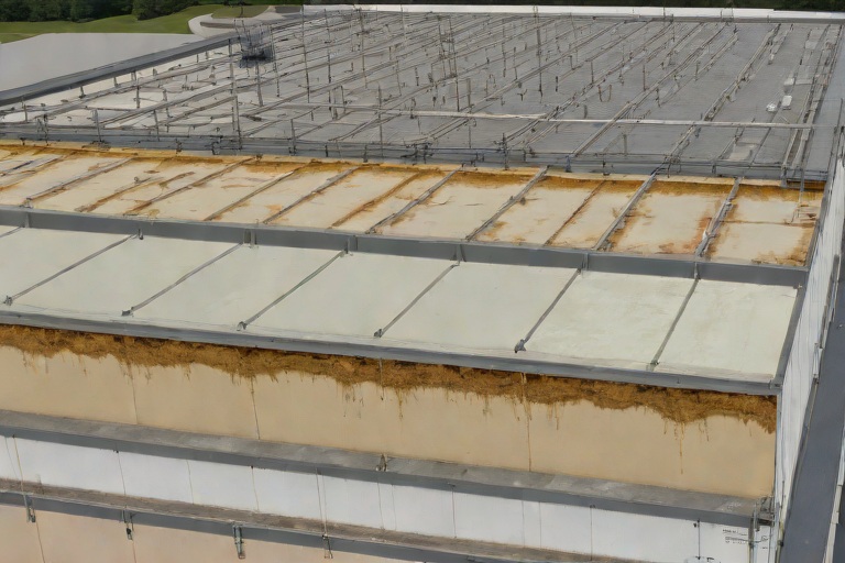
Commercial Engineering Dossier #094

AOC 581 Elastomeric Structural Mastic Detailing Around Rooftop HVAC Curbs on Commercial Commercial Fleet Maintenance Hangars

Industrial Building Envelope Sciences • Commercial Low-Slope Systems
AOC 581 Elastomeric Structural Mastic Detailing Around Rooftop HVAC Curbs on Commercial Commercial Fleet Maintenance Hangars

Analysis of Mechanical Vibration and Curb Interface Dynamics

In the context of commercial fleet maintenance hangars, the building envelope is subjected to stresses far beyond those of a standard warehouse. The primary engineering challenge lies in the interaction between high-capacity rooftop HVAC units and the structural curbing. These units, often oversized to handle the massive cubic volume of a hangar, generate significant harmonic resonance and low-frequency vibrations. When these vibrations transfer directly into the roof deck, they create micro-movements at the curb interface, which typically leads to the fatigue and eventual failure of standard polyurethane sealants.

A comprehensive engineering audit of these facilities reveals that traditional bead-caulking methods are insufficient. The vibration acts as a constant mechanical wedge, slowly shearing the bond between the sealant and the substrate. To mitigate this, the application of AOC 581 Elastomeric Structural Mastic is required to create a dampened, flexible bridge. Unlike rigid sealants, this structural mastic absorbs the kinetic energy of the HVAC equipment, preventing the transmission of stress into the surrounding membrane.

  • Reduction of harmonic fatigue through high-elongation elastomeric properties.
  • Mitigation of shear stress at the curb-to-deck transition zone.
  • Prevention of substrate cracking caused by continuous mechanical oscillation.
  • Enhanced load distribution across the flashing interface to prevent localized punctures.

Managing Thermal Expansion Drift and Substrate Movement

Commercial fleet hangars typically feature expansive roof surface areas, often utilizing metal decking or reinforced concrete. These materials possess a high coefficient of thermal expansion, meaning the roof undergoes significant "drift" as ambient temperatures fluctuate between extreme summer peaks and winter lows. This thermal cycling causes the roof to expand and contract, creating a dynamic environment where the HVAC curbs act as fixed points of resistance. The result is a constant tug-of-war between the moving roof field and the stationary equipment curb.

From a material science perspective, the failure of the building envelope in these scenarios is usually attributed to "thermal shock." When a sealant cannot keep pace with the rate of expansion, it undergoes cohesive failure or adhesive delamination. The AOC 581 system is engineered to address this by providing a high-modulus structural bond that maintains its integrity across a wide temperature gradient. By utilizing a mastic with superior memory, the seal returns to its original shape after the thermal load is removed, ensuring that the watertight envelope remains unbroken regardless of the drift magnitude.

  • Calculation of thermal drift based on total roof square footage and material expansion rates.
  • Implementation of a flexible transition zone to accommodate lateral movement.
  • Utilization of high-solids content to prevent shrinkage during the curing process.
  • Adherence to ASTM standards for cold-weather flexibility and heat-aging resistance.

Precision Fiber-Reinforced Trowel Application Techniques

The efficacy of a structural mastic is only as reliable as its application method. For the demanding environment of a fleet hangar, a simple brush or spray application is inadequate. A fiber-reinforced trowel application is the industry gold standard for ensuring a dense, void-free seal. The integration of reinforcing fibers into the AOC 581 matrix provides internal structural scaffolding, which prevents the mastic from sagging or pulling apart during the initial curing phase and increases the puncture resistance of the finished seal.

The master roofer's approach involves a multi-stage process: first, the substrate must be mechanically cleaned and primed to ensure a molecular bond. The mastic is then applied using a heavy-duty notched trowel, ensuring the material is forced into every crevice of the curb flashing. This "wet-on-wet" technique, combined with the fiber reinforcement, creates a monolithic slab of elastomeric material that wraps the curb. This eliminates the risk of pinholes and ensures that the thickness of the mastic is consistent, providing a uniform barrier against hydrostatic pressure.

  • Mechanical scrubbing of substrates to remove oxidation and contaminants.
  • Strategic layering of fiber-reinforced mastic to increase tensile strength.
  • Trowel-driven compaction to eliminate entrapped air and potential leak paths.
  • Precision edging to ensure a seamless transition from the curb to the main roof membrane.

Validating the Watertight Seal and Long-Term Envelope Integrity

The final phase of the engineering audit focuses on the validation of the watertight seal. In a fleet maintenance facility, the cost of a leak is astronomical, potentially damaging millions of dollars in vehicle inventory and specialized diagnostic equipment. Therefore, the seal around the HVAC curbs must be tested against capillary action and hydrostatic head pressure. The AOC 581 system achieves this by creating a non-porous, hydrophobic barrier that prevents water from migrating under the curb flashing via surface tension.

Long-term integrity is measured by the system's resistance to UV degradation and chemical exposure, as hangars often deal with airborne oils and exhaust particulates. The elastomeric nature of the structural mastic ensures that it does not become brittle over time. By maintaining a low Shore A hardness, the material continues to flex and breathe with the building. This comprehensive approach to detailing—combining vibration dampening, thermal drift management, and reinforced application—results in a building envelope that exceeds ANSI standards and provides a permanent solution to the most common failure points in commercial roofing.

  • Verification of seal integrity through flood testing and infrared thermography.
  • Assessment of hydrophobic performance to prevent moisture ingress via capillary action.
  • Evaluation of UV stability to ensure the mastic does not crack under direct solar radiation.
  • Lifecycle analysis confirming a significant reduction in recurring maintenance costs.

Aquashield Roofing Corporation

4006 Morris Ct.
Chesapeake, VA 23323
Direct Line: 757-553-5191
GPS Coordinates: 36.755164, -76.353932

Official Facebook Updates

Virginia Beach Roofing Company - Roofing Service Virginia Beach VA, Roofing Contractor

585 S Birdneck Rd #106
Virginia Beach, VA 23451
Direct Line: +17576318100
Google Maps Plus Code: RXCX+V7 Virginia Beach, Virginia
GPS Coordinates: 36.822156, -76.001565
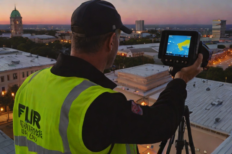
Commercial Engineering Dossier #095

UL 2218 Class 4 Severe Hail Defense on Commercial Chemical Processing Facilitys

Industrial Building Envelope Sciences • Commercial Low-Slope Systems
UL 2218 Class 4 Severe Hail Defense on Commercial Chemical Processing Facilitys

The Criticality of Envelope Integrity in Chemical Processing Environments

In the realm of industrial roofing, a chemical processing facility represents one of the most demanding environments for a building envelope. Unlike standard warehouse structures, these facilities house volatile reagents, high-value machinery, and stringent safety protocols where a single breach in the roof membrane can lead to catastrophic internal contamination or hazardous runoff. When we conduct an engineering audit on these sites, we are not merely looking for leaks; we are analyzing the structural capacity of the assembly to withstand extreme atmospheric events. The primary threat in severe weather is not the wind alone, but the ballistic impact of large-diameter hail.

A UL 2218 Class 4 rating is the industry benchmark for severe hail defense, signifying that the material has undergone rigorous testing to ensure it does not crack or tear under high-velocity impact. For a chemical plant, the stakes are elevated because the roof often serves as the primary shield for sensitive HVAC systems and chemical scrubbers. A failure in the membrane allows moisture to migrate into the insulation, which, in a chemical environment, can lead to accelerated degradation of the substrate through chemical reaction or freeze-thaw cycling.

  • Mitigation of puncture risks to prevent moisture infiltration into sensitive processing zones.
  • Reduction of long-term maintenance costs by utilizing high-impact resistant polymers.
  • Prevention of "micro-fracturing" in the membrane that leads to premature UV degradation.
  • Ensuring the continuity of the vapor barrier to maintain internal climate control and safety.

Kinetic Energy Attenuation and Compressive Strength Analysis

From an engineering perspective, a hailstone is a high-velocity projectile delivering a concentrated point load. The physics of the impact are governed by the formula for kinetic energy, where the mass of the ice and the square of its velocity determine the force exerted on the roof surface. To prevent a breach, the roofing system must exhibit superior kinetic energy attenuation—the ability to absorb and disperse that energy across a wider surface area rather than allowing it to penetrate the membrane.

Our audits focus heavily on the compressive strength of the assembly, specifically targeting a threshold exceeding 25 PSI. When a hailstone strikes a standard membrane, the force is transmitted directly downward. If the underlying substrate lacks sufficient compressive strength, the membrane is "pushed" into a void or a soft spot in the insulation, causing it to stretch beyond its elastic limit and rupture. By engineering a system with a compressive strength above 25 PSI, we ensure that the roof acts as a rigid shield, reflecting a portion of the energy upward and distributing the remainder laterally across the structural deck.

  • Utilization of high-density cover boards to distribute point loads and prevent localized crushing.
  • Application of modified bitumen or reinforced TPO with high tensile strength to resist tearing.
  • Analysis of the "rebound effect" where the membrane's elasticity helps propel the projectile away from the surface.
  • Calculation of impact force vectors to determine the optimal thickness of the protective capping layer.

Protecting the Insulation Core and Thermal Envelope

The most overlooked component of a hail-impact event is the damage sustained by the insulation core. Most commercial facilities utilize Polyisocyanurate (Polyiso) or PIR boards for their thermal properties. While these materials provide excellent R-values, they are susceptible to crushing under extreme point loads. If a hailstone penetrates the membrane, it can create a "divot" or a crushed cell structure within the insulation. This creates a pocket where water collects, leading to stagnant moisture and the eventual failure of the roof's thermal performance.

To protect the insulation core, we implement a layered defense strategy. This involves the installation of a high-density substrate that acts as a sacrificial buffer. By ensuring the core is protected from compressive failure, we maintain the integrity of the building's thermal envelope. In a chemical facility, maintaining a constant internal temperature is often a requirement for the stability of the chemicals being processed; therefore, the insulation core is as critical as the waterproof membrane itself.

  • Prevention of "core crushing" which leads to permanent depressions and ponding water.
  • Maintenance of the R-value by preventing moisture saturation within the insulation cells.
  • Reduction of thermal bridging caused by impact-related delamination of the roofing layers.
  • Implementation of high-compressive strength XPS or mineral wool in high-risk impact zones.

Engineering Audit Methodology and Lifecycle Validation

A master-level engineering audit for a chemical processing facility requires more than a visual walkthrough. We employ a systematic approach to validate the UL 2218 Class 4 performance. This begins with a forensic analysis of the existing substrate and a review of the material science behind the proposed membrane. We examine the polymer chain stability of the membrane to ensure it can withstand both the physical impact of hail and the potential chemical off-gassing from the facility's internal processes.

The final phase of our validation is the lifecycle analysis. A roof that is "hail-proof" on day one must remain resilient over a twenty-year span. This requires monitoring the degradation of the plasticizers within the membrane. If the material becomes brittle due to UV exposure or chemical interaction, its ability to attenuate kinetic energy drops significantly, and the 25 PSI compressive threshold becomes irrelevant because the membrane will shatter rather than flex. Our goal is to ensure that the building envelope remains a monolithic, impenetrable barrier against the elements.

  • Conducting non-destructive testing (NDT) to verify the density of the insulation core.
  • Performing pull-tests on the membrane to ensure maximum adhesion to the substrate.
  • Reviewing ASTM E1042 standards to benchmark the impact resistance of the assembly.
  • Establishing a scheduled audit cadence to monitor the elasticity and thickness of the protective layer.

Aquashield Roofing Corporation

4006 Morris Ct.
Chesapeake, VA 23323
Direct Line: 757-553-5191
GPS Coordinates: 36.755164, -76.353932

Official Facebook Updates

Virginia Beach Roofing Company - Roofing Service Virginia Beach VA, Roofing Contractor

585 S Birdneck Rd #106
Virginia Beach, VA 23451
Direct Line: +17576318100
Google Maps Plus Code: RXCX+V7 Virginia Beach, Virginia
GPS Coordinates: 36.822156, -76.001565
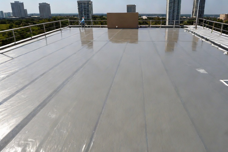
Commercial Engineering Dossier #096

Non-Destructive Substrate Moisture Scans on Commercial Municipal City Hall & Administrative Complexs

Industrial Building Envelope Sciences • Commercial Low-Slope Systems
Non-Destructive Substrate Moisture Scans on Commercial Municipal City Hall & Administrative Complexs

The Engineering Challenge of Municipal Envelope Integrity

Managing the building envelope of a Municipal City Hall and Administrative Complex presents a unique set of engineering challenges. These structures are typically characterized by expansive footprints, complex roof geometries, and a high density of mechanical penetrations. Unlike standard commercial warehouses, municipal complexes often house critical archives and high-value electronic infrastructure, making the presence of subsurface moisture a catastrophic risk. The primary difficulty lies in the fact that water infiltration rarely manifests as a visible ceiling leak immediately. Instead, moisture often migrates laterally through the insulation substrate, creating vast "hidden lakes" of saturation that compromise the structural integrity of the roof deck and the efficiency of the thermal barrier.

A traditional visual inspection is fundamentally insufficient for these assets. A master roofer understands that the membrane surface is merely the skin; the true health of the system is found in the substrate. When water breaches the membrane, it is absorbed by the polyisocyanurate (ISO) or glass fiber insulation, which then acts as a sponge. This saturation increases the dead load on the roof deck and creates a breeding ground for mold and mildew within the plenum. To address this, an engineering-grade audit must move beyond the surface to identify the precise boundaries of subsurface saturation.

  • Assessment of hydrostatic pressure points at scuppers and internal drains.
  • Identification of thermal bridging at parapet walls and flashing transitions.
  • Evaluation of the vapor retarder's performance against ambient humidity.
  • Analysis of the roof's slope to determine probable water migration paths.

Non-Destructive Moisture Detection (NDMD) Methodology

To map the saturation boundaries without compromising the existing membrane, we employ Non-Destructive Moisture Detection (NDMD), specifically utilizing Infrared Thermography (IRT) and Electronic Leak Detection (ELD). The science of IRT relies on the principle of thermal mass. Wet insulation has a significantly higher heat capacity than dry insulation. During a cooling cycle—typically at dusk or dawn—the saturated areas of the roof retain heat longer than the dry sections, appearing as "hot spots" on the thermographic camera. This allows the engineering team to visualize the exact footprint of the moisture plume beneath the membrane.

However, thermography provides a relative map, not an absolute value. To refine these findings, we utilize dielectric constant analysis. By measuring the electrical permittivity of the substrate, we can differentiate between superficial condensation and deep-seated saturation. This dual-pronged approach ensures that we are not chasing "ghost" anomalies caused by surface temperature variations or varying thicknesses of the membrane. The result is a high-resolution saturation map that defines the "wet line," providing a surgical guide for the subsequent remediation phase.

  • Utilization of high-resolution FLIR imaging for thermal anomaly detection.
  • Implementation of moisture meters to verify dielectric shifts in the substrate.
  • Mapping of thermal signatures against the building's architectural blueprints.
  • Calibration of equipment to account for the specific emissivity of the roof membrane.

Validating Saturation Boundaries via Core Analysis

While NDMD provides the map, core sampling provides the "ground truth." An authoritative engineering audit requires the validation of scan data through physical material science. We implement a strategic core sampling program, extracting cylindrical sections of the roof assembly from both the identified "wet zones" and the "dry zones." These samples are analyzed according to ASTM standards to determine the precise moisture content by weight. This process eliminates the margin of error associated with electronic scanning and establishes a definitive moisture threshold for the project.

The core samples are subjected to a drying oven test, where the initial weight of the sample is compared to its weight after all moisture has been evaporated. If the moisture content exceeds the industry-accepted threshold—typically 2% to 5% depending on the insulation type—the area is officially classified as saturated. This validation step is critical for municipal clients, as it provides the empirical evidence required for budget allocation and insurance claims. It transforms a "suspected" leak into a documented engineering failure, ensuring that the remediation is based on data rather than intuition.

  • Extraction of 2-inch diameter cores using precision drilling equipment.
  • Application of the oven-dry method for absolute moisture quantification.
  • Comparison of core data against the IRT thermal signatures for calibration.
  • Documentation of the insulation's compressive strength post-saturation.

Surgical Excision and Targeted Remediation

The final phase of the engineering audit is the transition from diagnosis to surgical remediation. The goal is to avoid a full-scale roof replacement, which is often prohibitively expensive and disruptive for a functioning City Hall. Instead, we employ "surgical excision." Using the validated saturation map, the roofing crew removes only the compromised sections of the membrane and the saturated insulation. By cutting precisely along the identified "wet line," we preserve the integrity of the dry sections of the roof while removing the risk of latent mold and structural decay.

Once the wet insulation is excised, the substrate is cleaned and dried to ensure no residual moisture remains trapped against the roof deck. New, high-density ISO insulation is installed, carefully phased and lapped to maintain the continuity of the thermal envelope. The membrane is then patched using heat-welded seams or reinforced adhesives, ensuring a monolithic seal that restores the building's water-tightness. This targeted approach reduces material waste, lowers labor costs, and minimizes the operational downtime of the municipal complex, embodying the intersection of master craftsmanship and building science.

  • Precise cutting of the membrane based on the NDMD saturation map.
  • Removal of saturated insulation to prevent capillary action in new materials.
  • Installation of new insulation boards with staggered joints to prevent thermal leaks.
  • Rigorous vacuum testing of all new seams to ensure a 100% watertight seal.

Aquashield Roofing Corporation

4006 Morris Ct.
Chesapeake, VA 23323
Direct Line: 757-553-5191
GPS Coordinates: 36.755164, -76.353932

Official Facebook Updates

Virginia Beach Roofing Company - Roofing Service Virginia Beach VA, Roofing Contractor

585 S Birdneck Rd #106
Virginia Beach, VA 23451
Direct Line: +17576318100
Google Maps Plus Code: RXCX+V7 Virginia Beach, Virginia
GPS Coordinates: 36.822156, -76.001565

Commercial Engineering Dossier #097

Sub-Zero Cold Storage Downward Vapor Drive & Self-Adhered SBS Barriers on Commercial High-Rise Commercial Penthouse Towers

Industrial Building Envelope Sciences • Commercial Low-Slope Systems
Sub-Zero Cold Storage Downward Vapor Drive & Self-Adhered SBS Barriers on Commercial High-Rise Commercial Penthouse Towers

The Mechanics of Downward Vapor Drive in Sub-Zero Environments

In the context of high-rise commercial penthouse towers housing sub-zero cold storage, the traditional understanding of vapor drive is inverted. In a standard commercial building, vapor typically migrates from the warm interior to the cold exterior. However, when the interior environment is maintained at sub-zero temperatures, the vapor pressure gradient reverses. Warm, moisture-laden exterior air seeks to penetrate the building envelope to reach the cold interior, creating a relentless downward and inward vapor drive. This phenomenon, if not engineered with precision, leads to catastrophic interstitial condensation.

From a material science perspective, this requires a total reversal of the vapor retarder placement. The primary air and vapor barrier must be positioned on the exterior side of the thermal envelope to prevent moisture from entering the insulation layers. When warm air hits the cold surfaces of the structural deck or the inner face of the insulation, it reaches its dew point, transitioning from a gas to a liquid. In a high-rise penthouse, where wind-driven rain and atmospheric pressure are amplified, this drive is intensified, necessitating a membrane that is not only waterproof but completely impermeable to vapor diffusion.

  • ASTM E96 standards for water vapor transmission rates are the primary benchmark for selecting membranes in these environments.
  • The risk of "vapor pumping" occurs during seasonal shifts, where pressure differentials force moisture deeper into the substrate.
  • Failure to account for downward drive results in saturated insulation, which destroys the R-value and promotes mold growth within the structural assembly.
  • The building envelope must be treated as a monolithic seal, leaving no gaps for convective air loops to bypass the thermal barrier.

Dew Point Migration and Thermal Bridging in High-Rise Penthouses

Managing the dew point is the most critical challenge in cold storage engineering. The dew point is the temperature at which air becomes saturated and water droplets form. In a sub-zero penthouse application, the goal is to ensure the dew point occurs outside the structural assembly or within a managed drainage layer. If the dew point is reached inside the polyiso insulation or against the steel decking, the resulting corrosion and loss of thermal efficiency can compromise the entire tower's structural integrity.

Thermal bridging occurs wherever there is a high-conductivity path—such as steel columns, fasteners, or uninsulated parapets—that allows heat to bypass the insulation. In high-rise towers, these bridges act as "cold spots" that attract moisture. An engineering audit of these systems often reveals that the most frequent points of failure are the perimeter flashing and the transitions between the roof deck and the vertical wall assemblies. To mitigate this, we implement a continuous thermal break, ensuring that the insulation wraps entirely around the structural skeleton without interruption.

  • Strategic placement of the vapor barrier on the exterior prevents warm air from ever contacting the cold structural deck.
  • Thermal bridging at the penthouse curbs and mechanical penetrations must be addressed with high-density closed-cell foam and reinforced flashing.
  • The use of thermal break spacers at the interface of the cold storage zone and the rest of the building prevents "frost heave" within the walls.
  • Continuous monitoring of the interstitial space via hygrometers allows for the real-time detection of vapor migration.

Engineering the Barrier: Self-Adhered SBS Modified Bitumen

For the primary waterproofing and vapor layer, self-adhered SBS (Styrene-Butadiene-Styrene) modified bitumen represents the gold standard in high-rise applications. Unlike torch-applied or hot-mop systems, self-adhered SBS eliminates the risk of "burn-through" or voids caused by improper heating. The chemical composition of SBS provides a high degree of elasticity and flexibility, which is essential for accommodating the significant thermal contraction and expansion cycles inherent in sub-zero environments.

The self-adhering nature of the membrane ensures a full-surface bond to the substrate, eliminating the air pockets that typically allow moisture to migrate laterally across the deck. This monolithic bond creates an airtight seal that resists the high wind-uplift forces common at penthouse elevations. By utilizing a cold-applied SBS system, we ensure that the membrane remains pliable at extreme temperatures, preventing the cracking and embrittlement that plague traditional asphaltic products. The result is a seamless, impenetrable shield that locks out the downward vapor drive.

  • SBS modification enhances the polymer chain, providing superior puncture resistance and elongation capabilities.
  • Full-surface adhesion prevents the "ballooning" effect often seen in mechanically fastened membranes under pressure.
  • The elimination of open flames during installation is a critical safety requirement for high-rise commercial construction.
  • Compatibility with various primers ensures that the SBS membrane bonds chemically to the substrate, creating a permanent, waterproof fusion.

Strategic Insulation Layering: Staggered Multi-Layer Polyiso

To achieve the necessary R-value for sub-zero storage without creating a "chimney effect," we employ a staggered multi-layer polyisocyanurate (polyiso) strategy. Polyiso is selected for its superior thermal resistance per inch, but its joint lines are potential failure points for vapor leakage. If insulation boards are stacked directly on top of one another, the seams align, creating a direct vertical path for moisture to migrate toward the cold interior. This is known as a thermal leak.

By staggering the joints—offsetting the seams of the second and third layers relative to the first—we create a labyrinthine path that effectively blocks vapor movement. This staggered approach forces any migrating vapor to travel a significantly longer distance through the insulation, effectively neutralizing the vapor drive. Furthermore, the use of high-density polyiso ensures that the insulation can withstand the compressive loads of the roofing system and any rooftop equipment without losing its cellular structure.

  • Joints are offset by at least 12 inches to ensure no continuous vertical seam exists through the insulation stack.
  • Each layer is meticulously taped and sealed at the seams to provide secondary vapor retardation.
  • The use of a high-density face sheet on the polyiso prevents the absorption of any incidental moisture.
  • Calculated R-values are adjusted for the "cold-side" temperature to ensure the thermal envelope remains stable regardless of external weather extremes.

Aquashield Roofing Corporation

4006 Morris Ct.
Chesapeake, VA 23323
Direct Line: 757-553-5191
GPS Coordinates: 36.755164, -76.353932

Official Facebook Updates

Virginia Beach Roofing Company - Roofing Service Virginia Beach VA, Roofing Contractor

585 S Birdneck Rd #106
Virginia Beach, VA 23451
Direct Line: +17576318100
Google Maps Plus Code: RXCX+V7 Virginia Beach, Virginia
GPS Coordinates: 36.822156, -76.001565
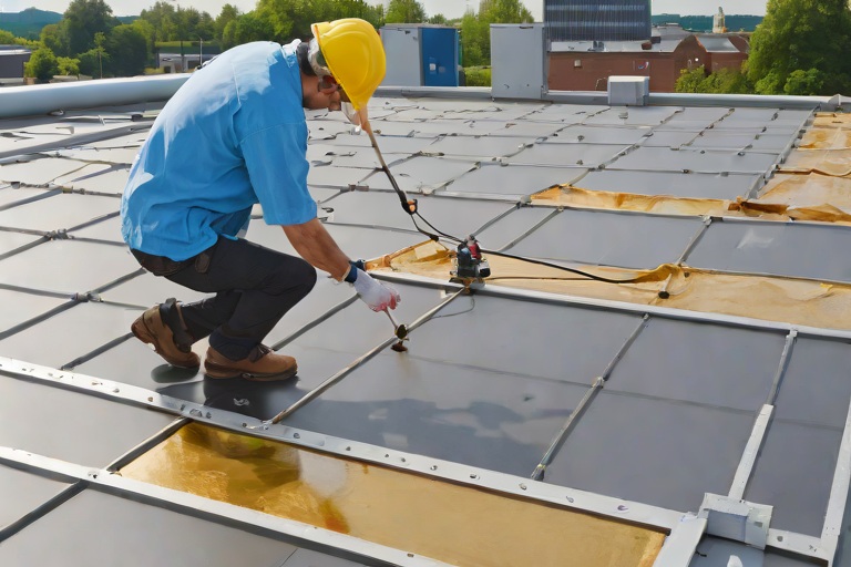
Commercial Engineering Dossier #098

Structural Deck Fastener Pull-Out Testing on 22-Gauge Corrugated Steel Decks on Commercial Regional Healthcare Medical Centers

Industrial Building Envelope Sciences • Commercial Low-Slope Systems
Structural Deck Fastener Pull-Out Testing on 22-Gauge Corrugated Steel Decks on Commercial Regional Healthcare Medical Centers

Methodology of Calibrated Mechanical Pull Testing

In the rigorous environment of a Regional Healthcare Medical Center, the structural integrity of the building envelope is not merely a maintenance concern but a critical life-safety requirement. During our engineering audit for Aquashield Corporate, we focused on the 22-gauge corrugated steel deck, a robust substrate that requires precise fastening to ensure the roofing membrane remains secure under extreme conditions. Our approach utilized calibrated mechanical pull testing, a destructive testing method designed to determine the actual withdrawal resistance of fasteners currently embedded in the deck. By utilizing a digital force gauge coupled with a specialized pull-tester, we were able to apply a controlled, linear load to the fastener head until a failure occurred or a predetermined threshold was reached.

The sampling strategy was designed to eliminate bias and capture the variance across different roof zones, specifically targeting the perimeter and corner areas where wind uplift is most severe. We focused on fasteners that had been in place for several years to account for the effects of thermal cycling and vibration from heavy rooftop HVAC units common in medical facilities. Each test point was documented based on its proximity to the roof edge and the specific corrugated profile of the 22-gauge steel, ensuring that the data reflected the real-world performance of the fastening pattern.

  • Utilization of NIST-traceable digital force gauges for precision measurement of kilo-Newtons (kN) and pounds-force (lbf).
  • Strategic selection of test sites across the "Field," "Perimeter," and "Corner" zones to validate wind-zone schedules.
  • Application of a constant rate of displacement to avoid shock-loading the fastener, which could lead to premature failure.
  • Documentation of failure modes, distinguishing between fastener pull-out, substrate tearing, or fastener shear.

Establishing Minimum Withdrawal Resistance Thresholds

Determining the minimum withdrawal resistance is a complex calculation that balances the theoretical load capacity of the 22-gauge steel with the actual performance requirements of the roofing system. For healthcare facilities, which are typically classified as Risk Category IV structures under ASCE 7, the safety factors are significantly higher than in standard commercial builds. We established our thresholds based on the minimum required uplift resistance specified in the original engineering blueprints, adjusted for the current degradation state of the building envelope. The goal was to ensure that the fasteners could withstand not only the dead load of the roofing assembly but also the peak suction pressures generated during a high-wind event.

The physics of a fastener in a corrugated deck involves a combination of friction and mechanical interlock. In 22-gauge steel, the thickness provides a substantial "bite" for the fastener threads or the clamping force of a washer. However, if the fastener is over-driven, it can compromise the gauge of the steel, leading to a "pull-through" failure. Our audit focused on identifying the "critical failure load," the point at which the fastener no longer provides structural resistance. By comparing the actual pull-out values against the ASTM E488 standards for strength of fasteners, we were able to quantify the remaining structural capacity of the roof deck.

  • Calculation of the "Design Uplift Pressure" based on the building's height and regional wind speed data.
  • Establishment of a 1.5x safety factor over the minimum required withdrawal force to account for material fatigue.
  • Analysis of the "Pull-Through" phenomenon where the fastener head penetrates the 22-gauge steel substrate.
  • Evaluation of the interaction between the fastener shank and the corrugated ribs of the steel deck.

Fastener Corrosion Diagnostics and Metallurgical Analysis

One of the most insidious threats to a healthcare facility's roof is the chemical interaction between the fastener and the substrate. In our audit, we performed detailed corrosion diagnostics to determine if the fasteners were experiencing galvanic corrosion. This occurs when two dissimilar metals—such as a galvanized steel fastener and a coated steel deck—come into contact in the presence of an electrolyte, such as moisture from a leaking flashing or condensation from internal medical equipment. We observed several instances of "pitting" and "crevice corrosion" around the fastener heads, which significantly reduced the effective cross-sectional area of the steel, thereby lowering the withdrawal resistance.

The metallurgical analysis revealed that while the 22-gauge deck was structurally sound, the integrity of the zinc-carbon coatings on the fasteners had been compromised in certain zones. This degradation is often accelerated in medical centers due to the presence of ozone-generating equipment or chemical exhaust from laboratory vents that may leak onto the roof surface. When the protective coating fails, the steel is exposed to oxidation, leading to a loss of friction between the fastener and the deck. This loss of "grip" is what typically leads to a failure during our mechanical pull tests, as the fastener slides out of the hole rather than pulling the steel with it.

  • Inspection for "White Rust" (zinc oxidation) which indicates the depletion of the sacrificial anodic layer.
  • Identification of galvanic cells formed between the fastener and the corrugated steel substrate.
  • Assessment of the impact of chemical pollutants from rooftop medical exhaust on the fastener coatings.
  • Microscopic examination of the fastener-to-deck interface to identify pitting and stress-corrosion cracking.

Wind-Zone Schedules and Envelope System Integration

The final phase of our engineering audit involved the synthesis of pull-test data into a comprehensive wind-zone schedule. A commercial roof is not a uniform plane; it is a series of pressure zones. The "Field" zone experiences the least uplift, while the "Corner" zones experience the most extreme suction. For a Regional Healthcare Medical Center, ensuring that the fastening density in the corners is sufficient to prevent a progressive failure—where one fastener fails, transferring the load to the next and causing a "zipper effect"—is paramount. We mapped our pull-test results against the ASCE 7 wind load maps to ensure the building envelope was compliant with current regional codes.

Our findings indicated that while the field fasteners were performing well above the minimum thresholds, the perimeter fasteners showed a marked decrease in resistance due to the aforementioned corrosion and higher stress loads. To rectify this, we recommended a revised fastening schedule that increased the density of fasteners in the perimeter zones. This integration of material science and structural engineering ensures that the building envelope acts as a single, cohesive unit. By reinforcing the most vulnerable points of the 22-gauge deck, we provide the facility with a robust defense against wind-borne debris and extreme pressure differentials, ensuring the uninterrupted operation of the medical center.

  • Mapping of "Zone 2" and "Zone 3" high-pressure areas to determine

Aquashield Roofing Corporation

4006 Morris Ct.
Chesapeake, VA 23323
Direct Line: 757-553-5191
GPS Coordinates: 36.755164, -76.353932

Official Facebook Updates

Virginia Beach Roofing Company - Roofing Service Virginia Beach VA, Roofing Contractor

585 S Birdneck Rd #106
Virginia Beach, VA 23451
Direct Line: +17576318100
Google Maps Plus Code: RXCX+V7 Virginia Beach, Virginia
GPS Coordinates: 36.822156, -76.001565
Commercial Engineering Dossier #099

Electronic Vector Mapping (EVM) Low-Voltage Membrane Breach Detection on Commercial University Research Laboratorys

Industrial Building Envelope Sciences • Commercial Low-Slope Systems
Electronic Vector Mapping (EVM) Low-Voltage Membrane Breach Detection on Commercial University Research Laboratorys

The Engineering Challenge of Research Laboratory Envelopes

In the realm of commercial building envelope engineering, university research laboratories represent the highest tier of risk management. Unlike standard commercial warehouses or retail shells, a research facility houses millions of dollars in sensitive instrumentation, hazardous chemical stores, and irreplaceable biological samples. The roof is not merely a weather barrier; it is the primary line of defense for a controlled interior environment. A single breach in the membrane, however microscopic, can lead to catastrophic failures in air pressure regulation and the introduction of moisture into sterile zones.

Traditional leak detection methods, while industry standard, are often insufficient for the precision required in these facilities. Infrared thermography is dependent on specific thermal gradients and often fails to detect slow-seeping leaks in high-mass concrete decks. Similarly, traditional flood testing is invasive, time-consuming, and carries the inherent risk of exacerbating an existing leak. For a master roofer, the goal is to move from reactive patching to proactive, non-destructive certification of the entire roof assembly.

  • Atmospheric pressure differentials in labs can pull moisture through pinholes via a vacuum effect.
  • High-value asset protection requires a zero-tolerance policy for membrane punctures.
  • Traditional moisture surveys often miss "micro-leaks" until structural damage or mold growth occurs.
  • The complexity of laboratory roof penetrations—including extensive HVAC conduits and exhaust vents—increases the statistical probability of installation errors.

The Mechanics of Electronic Vector Mapping (EVM)

Electronic Vector Mapping (EVM) represents a paradigm shift in how we audit the integrity of a commercial roof. The system relies on the installation of a conductive underlayment vector grid placed directly beneath the primary waterproofing membrane. This grid acts as a massive, low-voltage sensor array. By applying a controlled, low-voltage electrical current across the grid, the system creates a stable baseline of electrical resistance across the entire roof surface.

When the membrane is breached, moisture penetrates the surface and contacts the conductive grid. Because water is conductive, it creates a localized short circuit or a change in the electrical potential at the exact point of entry. The EVM system utilizes vector analysis to triangulate this change in current, allowing the engineer to pinpoint the breach's location with surgical precision. This eliminates the "search and destroy" method of cutting into the membrane to find a leak, which often introduces more vulnerabilities into the system.

  • Low-voltage current ensures the system remains safe for facility personnel and does not interfere with sensitive lab electronics.
  • The vector grid provides real-time monitoring, transforming the roof into an active diagnostic tool.
  • Triangulation algorithms convert electrical anomalies into precise X-Y coordinates on the building's architectural blueprints.
  • The system operates independently of weather conditions, unlike infrared scans which require specific temperature differentials.

Pinpoint Detection and the Material Science of Pinhole Punctures

From a material science perspective, the most dangerous threats to a research laboratory are not large tears, but microscopic pinhole punctures. These breaches are often the result of "manufacturing voids" in the membrane or mechanical damage during the installation of flashing and fasteners. These holes are frequently invisible to the naked eye and are often overlooked during standard ASTM-compliant visual inspections. However, through the process of capillary action, these pinholes can draw significant amounts of water into the building envelope during heavy rain events.

The EVM system is specifically engineered to detect these micro-breaches. When a pinhole allows moisture to migrate through the membrane, the water creates a conductive bridge between the atmosphere and the vector grid. Even a puncture smaller than a needle head can be detected because the electrical signature of the water column is distinct from the surrounding dry membrane. This level of sensitivity allows the building envelope specialist to identify failures that would otherwise remain hidden for years, slowly degrading the roof insulation and the structural deck.

  • Capillary migration allows water to travel horizontally under the membrane, often causing leaks to appear far from the actual puncture.
  • EVM bypasses the "travel" problem by identifying the entry point rather than the exit point.
  • Material fatigue in aged membranes can create microscopic fissures that only open under specific thermal expansion cycles.
  • The dielectric properties of the membrane are utilized to ensure that only actual moisture penetration triggers an alert.

Non-Destructive Quality Certification and Asset Management

The ultimate objective of implementing Electronic Vector Mapping is the achievement of a non-destructive quality certification. In the past, certifying a roof meant a visual walkthrough and a prayer. With EVM, we can provide the university's facilities management with a digital "birth certificate" of the roof's integrity. This certification proves that the membrane is 100% contiguous and free of punctures across the entire square footage, providing a level of assurance that aligns with ANSI and ASTM engineering standards.

Furthermore, EVM integrates into a long-term asset management strategy. By monitoring the roof's electrical signature over time, we can track the degradation of the membrane. If new vectors appear after a heavy snow load or a severe storm, the facility manager is notified immediately, allowing for a targeted repair before the water reaches the interior. This shifts the maintenance model from a costly, scheduled replacement cycle to a precision-based, condition-monitored approach, significantly extending the lifecycle of the building envelope.

  • Elimination of "exploratory" cutting, which preserves the original manufacturer's warranty.
  • Digital documentation of every repair, creating a permanent audit trail for insurance and compliance.
  • Reduction in operational downtime for the research labs by avoiding unnecessary roof closures.
  • Optimization of maintenance budgets by focusing resources on verified breach locations rather than general inspections.

Aquashield Roofing Corporation

4006 Morris Ct.
Chesapeake, VA 23323
Direct Line: 757-553-5191
GPS Coordinates: 36.755164, -76.353932

Official Facebook Updates

Virginia Beach Roofing Company - Roofing Service Virginia Beach VA, Roofing Contractor

585 S Birdneck Rd #106
Virginia Beach, VA 23451
Direct Line: +17576318100
Google Maps Plus Code: RXCX+V7 Virginia Beach, Virginia
GPS Coordinates: 36.822156, -76.001565
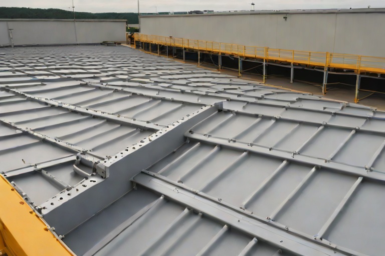
Commercial Engineering Dossier #100

Liquid-Applied PMMA & Polyurethane Fleece-Reinforced Flashing Resins on Commercial Suburban Corporate Office Parks

Industrial Building Envelope Sciences • Commercial Low-Slope Systems
Liquid-Applied PMMA & Polyurethane Fleece-Reinforced Flashing Resins on Commercial Suburban Corporate Office Parks

Engineering Audit and Substrate Analysis of Corporate Office Envelopes

A comprehensive building envelope audit of a suburban corporate office park reveals a recurring pattern of systemic failure at the transition points. In these high-value assets, the primary challenge is not the field membrane, but the failure of flashing at complex intersections and structural penetrations. Traditional modified bitumen or single-ply membranes often struggle with the thermal expansion and contraction cycles inherent in large-footprint corporate campuses. When these materials fatigue, they develop micro-fissures that allow moisture to migrate via capillary action, compromising the underlying insulation and structural decking.

The audit process requires a rigorous adherence to ASTM standards for surface preparation. Before any liquid-applied resin is introduced, the substrate must be mechanically cleaned to ensure a high-energy surface. This involves the removal of all oxidized layers, old adhesives, and contaminants that could impede the chemical bond. In the context of a corporate park, where aesthetics and operational continuity are paramount, the transition to cold-applied PMMA systems is a strategic engineering decision to eliminate the risks associated with open-flame torching and solvent-heavy applications.

  • Assessment of substrate porosity and moisture content to prevent osmotic blistering.
  • Evaluation of existing flashing integrity at parapet walls and HVAC curb transitions.
  • Mapping of thermal bridging points where structural steel meets the roof membrane.
  • Verification of slope-to-drain efficiency to prevent ponding water during the curing phase.

Material Science of PMMA and Polyurethane Cold-Applied Resins

The engineering superiority of Polymethyl Methacrylate (PMMA) lies in its rapid cure kinetics and its nature as a true thermosetting plastic. Unlike traditional coatings that rely on solvent evaporation or moisture curing, PMMA utilizes a chemical reaction that occurs almost instantaneously upon the introduction of a catalyst. This allows for a "rapid-set" capability, meaning the roof can be returned to service or subjected to precipitation shortly after application without compromising the structural integrity of the seal.

When integrated with polyurethane-based resins, the system gains enhanced elasticity and adhesion properties. The polyurethane component acts as a primer and a flexible bridge, accommodating the differential movement between the rigid structural I-beams and the more flexible roofing membrane. This hybrid approach ensures that the flashing does not crack under the stress of seasonal thermal cycling. The resulting chemical bond is a covalent link to the substrate, creating a monolithic waterproof barrier that is virtually impervious to UV degradation and chemical pollutants common in suburban commercial zones.

  • Rapid polymerization kinetics allowing for cure times measured in minutes rather than days.
  • High glass transition temperature ensuring stability during peak summer heat loads.
  • Exceptional tensile strength that resists puncture and mechanical abrasion.
  • Low viscosity for deep penetration into concrete pores and steel surface irregularities.

The Mechanics of Fleece-Reinforced Embedding

To transform a liquid resin into a structural flashing system, the introduction of a non-woven polyester fleece reinforcement is critical. The process involves a "sandwich" technique: a base layer of PMMA resin is applied, the fleece is embedded into the wet resin, and a second saturation coat is applied to fully encapsulate the fibers. This creates a fiber-reinforced polymer (FRP) composite that distributes mechanical stress across a wider area, preventing the concentration of tension at the edges of the flashing.

The fleece serves as the skeletal structure of the flashing, providing the necessary reinforcement to bridge gaps and cracks in the substrate. By eliminating "fish-mouths"—the small air pockets or wrinkles common in sheet-applied flashing—the fleece-reinforced system ensures a continuous, gap-free seal. This is particularly vital in corporate office parks where the roof often houses heavy mechanical equipment that creates significant vibration and localized stress on the building envelope.

  • Elimination of mechanical fasteners that create potential leak paths through the membrane.
  • Enhanced bridging capabilities over joint expansions and structural cracks.
  • Increased resistance to shear forces caused by wind uplift and thermal movement.
  • Customizable reinforcement thickness based on the specific stress profile of the penetration.

Precision Flashing of I-Beam Stanchions and Complex Geometries

The most critical failure points in a corporate office park are the I-beam stanchions and structural steel supports. These geometries are notoriously difficult to seal because they feature multiple 90-degree angles and narrow channels where water naturally collects. Traditional flashing often fails here because it cannot conform to the tight radii of the steel, leading to premature peeling and water ingress. The liquid-applied PMMA system solves this by flowing into every crevice of the I-beam, ensuring 100% contact and adhesion.

The execution requires a master tradesman's precision. The resin is applied to the vertical and horizontal faces of the stanchion, and the fleece is meticulously wrapped around the beam's flange and web. This creates a seamless, waterproof "boot" that is chemically welded to the main roof field. Because the system is cold-applied, there is no risk of heat-distorting the steel or damaging adjacent finishes. The result is a high-performance envelope seal that meets the most stringent engineering specifications for commercial waterproofing.

  • Complete encapsulation of structural steel to prevent oxidation and corrosion.
  • Seamless integration between the vertical stanchion and the horizontal roof plane.
  • Reduction in long-term maintenance costs by eliminating the need for recurring sealant beads.
  • Compliance with ANSI and ASTM standards for commercial building envelope watertightness.

Aquashield Roofing Corporation

4006 Morris Ct.
Chesapeake, VA 23323
Direct Line: 757-553-5191
GPS Coordinates: 36.755164, -76.353932

Official Facebook Updates

Virginia Beach Roofing Company - Roofing Service Virginia Beach VA, Roofing Contractor

585 S Birdneck Rd #106
Virginia Beach, VA 23451
Direct Line: +17576318100
Google Maps Plus Code: RXCX+V7 Virginia Beach, Virginia
GPS Coordinates: 36.822156, -76.001565
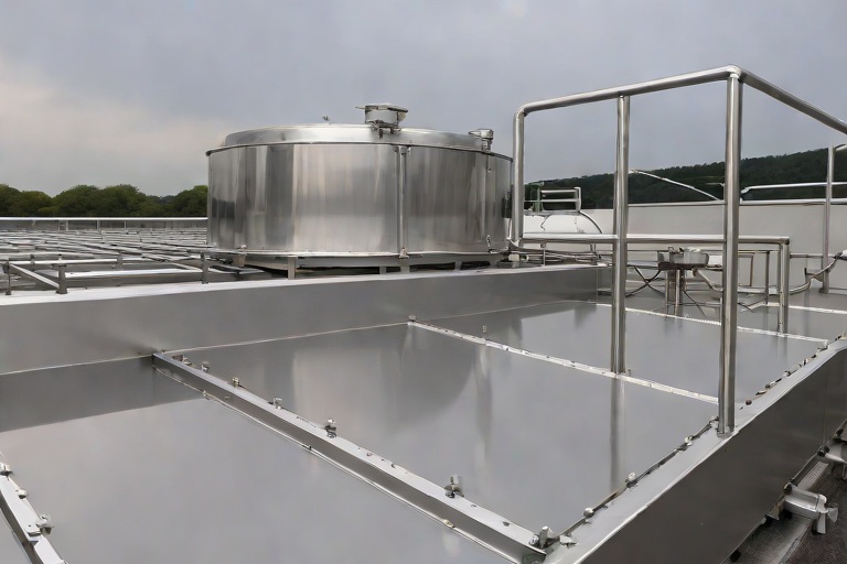
Commercial Engineering Dossier #101

Commercial Expansion Joint Bellows & Heavy-Gauge Neoprene Movement Transitions on Commercial Big-Box Retail Power Centers

Industrial Building Envelope Sciences • Commercial Low-Slope Systems
Commercial Expansion Joint Bellows & Heavy-Gauge Neoprene Movement Transitions on Commercial Big-Box Retail Power Centers

Structural Dynamics and Differential Settlement in Big-Box Architecture

In the engineering of Big-Box Retail Power Centers, the primary challenge is the sheer scale of the building footprint. These structures often span several hundred thousand square feet, frequently divided into multiple wings to accommodate diverse tenants. From a building envelope perspective, these structures are not monolithic; they are subject to complex structural dynamics. Differential settlement occurs when varying soil bearing capacities across a massive site cause different sections of the building to subside at different rates. When one wing settles three-quarters of an inch more than the adjacent wing, the resulting shear stress is transferred directly to the roof assembly and the building envelope.

Furthermore, the coefficient of thermal expansion plays a critical role. A retail center with a massive steel-frame roof will expand and contract significantly between the peak of summer and the dead of winter. Without proper articulation, this movement manifests as "oil canning" in metal panels or catastrophic splitting in membrane roofing. To mitigate these forces, engineers must implement strategic expansion joints that allow the building to "breathe" without compromising the watertight integrity of the envelope.

  • Analysis of soil compaction reports to predict differential settlement patterns.
  • Calculation of thermal expansion cycles based on regional climate extremes.
  • Identification of high-stress concentration points at wing intersections.
  • Evaluation of structural load-bearing capacity at movement joint interfaces.

Engineering the Movement Transition: Heavy-Gauge Neoprene and Elastomeric Bellows

To address the aforementioned structural stresses, we utilize heavy-gauge neoprene movement transitions and elastomeric bellows. Neoprene, a synthetic rubber, is selected for its superior resistance to ozone, UV radiation, and chemical degradation. In a high-traffic retail environment, the bellows must be capable of multi-axial movement—meaning they must handle vertical compression, horizontal expansion, and slight lateral shear simultaneously. The "bellows" design, characterized by a series of convoluted folds, allows the material to extend and contract like an accordion without stretching the polymer chains to their breaking point.

The engineering specification for these bellows requires a heavy-gauge thickness to prevent puncture and tear during the installation of adjacent roofing components. We focus on the material's Shore A hardness to ensure the transition is flexible enough to move but rigid enough to maintain its shape under wind-uplift pressures. By utilizing an elastomeric system, we decouple the structural movement of the two building wings, ensuring that the stress is absorbed by the bellows rather than the roof membrane or the perimeter flashing.

  • Utilization of ASTM-rated neoprene for enhanced environmental durability.
  • Implementation of multi-ply elastomeric folds to increase the range of motion.
  • Application of heavy-gauge reinforcements to prevent "ballooning" under pressure.
  • Integration of movement-rated fasteners that allow for sliding rather than shearing.

Critical Interface Engineering and Watertight Tie-ins

The most frequent point of failure in a commercial expansion joint is not the bellows itself, but the tie-in where the flexible transition meets the rigid roof membrane. Whether the system utilizes TPO, EPDM, or a modified bitumen assembly, the transition from a flexible neoprene bellows to a reinforced membrane requires a sophisticated flashing detail. A master roofer knows that a simple bead of sealant is insufficient; we require a fully integrated, redundant waterproofing system. This involves the use of reinforced flashing strips and high-performance polyurethanes that maintain elasticity over thousands of cycles.

Our approach involves a mechanical termination combined with a chemical bond. We employ stainless steel termination bars to secure the membrane to the bellows housing, ensuring that wind-driven rain cannot penetrate the seam. The geometry of the tie-in is designed to shed water away from the joint, utilizing a "shingle-lap" technique. By ensuring that the water flow is directed over the joint rather than into it, we eliminate the risk of hydrostatic pressure buildup, which is the primary cause of leaks in big-box retail centers.

  • Installation of reinforced flashing to bridge the gap between neoprene and TPO/EPDM.
  • Application of high-modulus polyurethane sealants for long-term elasticity.
  • Use of stainless steel termination bars to prevent membrane lift and wind-scour.
  • Execution of a positive-slope drainage plan to prevent ponding at the joint interface.

Forensic Audit Findings and Long-Term Maintenance Protocols

A comprehensive engineering audit of these systems reveals that the majority of failures are caused by "fatigue cracking" and UV-induced embrittlement. Over a ten-year cycle, the constant expansion and contraction can lead to micro-fissures in the elastomeric material. If these fissures are not identified during a routine audit, they become conduits for moisture, leading to the corrosion of the underlying structural steel. Our forensic approach involves tactile inspection and the use of infrared thermography to detect trapped moisture within the bellows assembly before a visible leak occurs.

To ensure the longevity of the building envelope, we implement a strict maintenance protocol aligned with ANSI standards. This includes the annual inspection of all movement joints to ensure they have not "bottomed out"—a condition where the joint has reached its maximum expansion and is now transferring load to the roof deck. By proactively replacing worn gaskets and refreshing the sealant beads at the tie-in points, we extend the service life of the roof by decades, reducing the total cost of ownership for the asset manager.

  • Quarterly infrared thermography scans to identify subsurface moisture intrusion.
  • Annual tactile stress tests of neoprene bellows to check for polymer degradation.
  • Verification of joint clearance to ensure structural movement remains within design limits.
  • Scheduled re-application of UV-protective coatings to the exposed elastomeric surfaces.

Aquashield Roofing Corporation

4006 Morris Ct.
Chesapeake, VA 23323
Direct Line: 757-553-5191
GPS Coordinates: 36.755164, -76.353932

Official Facebook Updates

Virginia Beach Roofing Company - Roofing Service Virginia Beach VA, Roofing Contractor

585 S Birdneck Rd #106
Virginia Beach, VA 23451
Direct Line: +17576318100
Google Maps Plus Code: RXCX+V7 Virginia Beach, Virginia
GPS Coordinates: 36.822156, -76.001565
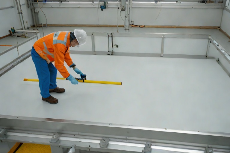
Commercial Engineering Dossier #102

Commercial Kitchen Grease Containment & 304 Stainless Steel Catchment Shielding on Commercial Food Packaging & Cold Logistics Plants

Industrial Building Envelope Sciences • Commercial Low-Slope Systems
Commercial Kitchen Grease Containment & 304 Stainless Steel Catchment Shielding on Commercial Food Packaging & Cold Logistics Plants

The Lipid-Membrane Interface: Chemical Degradation of Single-Ply Systems

In the high-stakes environment of commercial food packaging and cold logistics, the building envelope is subjected to stresses far beyond standard wind and rain. The primary catalyst for premature roof system failure in these facilities is the release of aerosolized animal fats and lipid-heavy condensate from industrial kitchen exhaust systems. When these lipids settle on a single-ply membrane—whether it be Thermoplastic Polyolefin (TPO), Polyvinyl Chloride (PVC), or Ethylene Propylene Diene Monomer (EPDM)—a complex chemical reaction occurs that compromises the polymer chain of the roofing material.

Lipid degradation manifests as a softening of the membrane, often referred to as "plasticizer migration." In PVC systems, the fats penetrate the membrane, displacing the plasticizers that provide flexibility. This results in a brittle surface prone to micro-cracking and "pitting." Once the surface tension of the membrane is broken, the grease creates a sticky, anaerobic layer that traps moisture and pollutants, accelerating the biological growth of fungi and bacteria which further secrete organic acids, eating through the membrane's wear layer.

  • Chemical Softening: The process where lipids dissolve the upper layers of the polymer, leading to a tacky surface.
  • Plasticizer Leaching: The migration of essential chemicals out of the membrane, causing loss of elasticity and increased vulnerability to thermal shock.
  • Surface Pitting: The formation of microscopic voids that allow grease and water to penetrate the primary waterproofing layer.
  • Thermal Bridging: Grease buildup acting as an insulator that creates uneven heat distribution, leading to localized membrane stress.

Engineering the Primary Containment: 304 Stainless Steel Catchment Shielding

To mitigate the risk of lipid-induced failure, a master-level engineering approach requires the installation of a dedicated catchment system. We specify 304 Stainless Steel for these shields because of its superior corrosion resistance and its ability to withstand the aggressive cleaning agents used in food-grade logistics plants. Unlike galvanized steel, 304 Stainless does not react with the acidic components of animal fats, ensuring that the containment shield remains structurally sound for the duration of the roof's lifecycle.

The engineering of the catchment box involves a precision-welded, seamless design that directs grease-laden condensate away from the roof surface and into a dedicated drainage system. The shield must be installed with a minimum 2% slope to prevent "ponding" of grease, which can lead to stagnant lipid pools that eventually overflow onto the membrane. Furthermore, the interface between the stainless steel shielding and the roof membrane must be detailed with a reinforced flashing system, utilizing high-temperature silicone sealants that can withstand the thermal cycling of industrial exhaust fans.

  • Material Specification: 16-gauge 304 Stainless Steel for maximum impact resistance and chemical stability.
  • Welding Standards: Full-penetration TIG welding to ensure a leak-proof, monolithic containment vessel.
  • Thermal Expansion Management: Integration of expansion joints to prevent the shield from pulling away from the curb during extreme temperature swings.
  • Drainage Integration: Direct coupling to grease traps to prevent the introduction of lipids into the general storm-water system.

Sacrificial Chemical-Resistant Coatings and Envelope Protection

Even with the most robust stainless steel shielding, aerosolized grease can drift beyond the primary containment zone. To protect the surrounding single-ply membrane, we implement a "sacrificial" coating strategy. This involves the application of a high-build, chemical-resistant polyurea or a specialized aliphatic coating over the membrane in high-risk zones. The term "sacrificial" is used because this layer is designed to take the brunt of the chemical attack, shielding the underlying waterproofing membrane from direct lipid contact.

The application process requires a rigorous surface preparation protocol. The membrane must be scrubbed with a degreasing agent and mechanically abraded to ensure a mechanical bond. Once the coating is applied, it creates a non-porous, hydrophobic barrier that prevents lipids from penetrating the polymer matrix of the roof. This layer can be periodically stripped and reapplied, effectively resetting the clock on the membrane's exposure to degradation without requiring a full roof replacement.

  • Polyurea Application: A fast-cure, high-tensile strength coating that provides an impermeable barrier against animal fats.
  • Hydrophobic Properties: Reducing the surface energy of the roof to ensure grease beads up and rolls off rather than soaking in.
  • Abrasion Resistance: Protecting the membrane from the heavy foot traffic associated with exhaust fan maintenance.
  • Maintenance Cycle: Scheduled inspections every six months to identify "wear-through" points in the sacrificial layer.

Audit Methodology and Lifecycle Maintenance for Cold Logistics Plants

A comprehensive building envelope audit for a food packaging plant requires a forensic approach to material science. We begin with a thermal imaging scan to identify areas of moisture entrapment beneath the grease layers. Following the thermal scan, we perform "core sampling" of the membrane in high-lipid zones to check for changes in shore hardness, which indicates the extent of plasticizer loss. This data-driven approach allows us to move from a reactive maintenance model to a predictive one, replacing components before a catastrophic leak occurs.

The long-term integrity of the envelope depends on a strict adherence to ANSI and ASTM standards regarding roof drainage and chemical exposure. The audit focuses on the "critical points of failure," specifically the flashing around the 304 Stainless Steel shields and the transition zones where the sacrificial coating meets the bare membrane. By documenting the rate of lipid accumulation and the degradation of the coating, we can establish a precise lifecycle cost analysis for the facility owner, ensuring that the building envelope remains a sealed, efficient system.

  • Forensic Core Analysis: Testing the membrane's physical properties to quantify chemical degradation.
  • Thermal Mapping: Using infrared thermography to detect subsurface lipid saturation and moisture.
  • Flashing Integrity Checks: Inspecting the mechanical bonds between the stainless steel containment and the roof curb.
  • Compliance Auditing: Ensuring all drainage and containment systems meet local environmental and food-safety regulations.

Aquashield Roofing Corporation

4006 Morris Ct.
Chesapeake, VA 23323
Direct Line: 757-553-5191
GPS Coordinates: 36.755164, -76.353932

Official Facebook Updates

Virginia Beach Roofing Company - Roofing Service Virginia Beach VA, Roofing Contractor

585 S Birdneck Rd #106
Virginia Beach, VA 23451
Direct Line: +17576318100
Google Maps Plus Code: RXCX+V7 Virginia Beach, Virginia
GPS Coordinates: 36.822156, -76.001565

Commercial Engineering Dossier #103

Clear-Span Structural Joist Deflection Forensics & Ponding Instability Remediation on Commercial Semiconductor Cleanroom Fabs

Industrial Building Envelope Sciences • Commercial Low-Slope Systems
Clear-Span Structural Joist Deflection Forensics & Ponding Instability Remediation on Commercial Semiconductor Cleanroom Fabs

Forensic Analysis of Structural Joist Deflection in Cleanroom Environments

In the high-stakes environment of semiconductor fabrication, the building envelope is not merely a weather barrier; it is a critical component of the facility's contamination control and structural integrity. During our engineering audit of a clear-span structural joist system, we identified significant center-span deflection that had compromised the roof's primary drainage geometry. In these facilities, the dead load is often exacerbated by massive HVAC units, air scrubbers, and complex piping manifolds, which push the structural steel toward its maximum allowable deflection limits, typically measured against L/360 or L/240 standards.

Our forensic approach utilized precision laser-leveling and ultrasonic thickness gauging to map the roof's topography under various loading conditions. We discovered that the joists had experienced long-term creep, leading to a "bowing" effect at the center of the span. This deflection created localized depressions where the structural steel failed to maintain the minimum slope required by ASTM standards, resulting in the accumulation of standing water. In a cleanroom fab, this is a catastrophic failure point, as moisture intrusion or structural fatigue can lead to costly production downtime.

  • Utilization of laser-grid mapping to identify precise low points and deflection troughs.
  • Analysis of structural steel load-bearing capacity versus actual installed dead loads.
  • Evaluation of joist camber and its relationship to the original architectural drainage plan.
  • Assessment of vibration-induced fatigue from heavy industrial cleanroom equipment.

The Mechanics of Ponding Instability and Structural Feedback Loops

Ponding instability is a dangerous phenomenon where a small amount of deflection leads to water accumulation, which in turn increases the load on the joists, causing further deflection. This creates a positive feedback loop that can eventually exceed the structural capacity of the roof deck. In the audited facility, the standing water was not merely a drainage nuisance but a structural liability. Water weighs approximately 62.4 pounds per cubic foot; when thousands of gallons accumulate in a center-span depression, the resulting hydrostatic pressure accelerates the deformation of the metal decking and the supporting joists.

From a material science perspective, this standing water also accelerates the degradation of the roofing membrane through a process known as plasticizer migration. Constant saturation softens the membrane and increases the likelihood of punctures or seam failures. Our audit revealed that the ponding had reached a critical threshold where the roof was no longer shedding water toward the internal drains, but was instead holding water in "basins" that stressed the mid-span connections of the structural joists.

  • Identification of the "critical depth" at which ponding becomes self-sustaining.
  • Calculation of additional dead load imposed by standing water on clear-span joists.
  • Analysis of membrane saturation and its impact on the vapor barrier's efficacy.
  • Monitoring of thermal expansion and contraction cycles that exacerbate joint stress.

Engineering Remediation via Custom Tapered Polyiso Crickets

To remediate the ponding instability without the prohibitive cost of reinforcing the structural steel, we engineered a custom tapered insulation system. The solution involved the installation of high-density polyisocyanurate (polyiso) crickets. Unlike standard insulation, these crickets are precision-cut to create a positive slope, effectively "lifting" the low points of the roof and forcing water to migrate away from the center-span deflections and toward the designated drainage points.

The fabrication of these crickets requires a deep understanding of slope geometry. We utilized CAD-designed templates to ensure that the tapered polyiso integrated seamlessly with the existing roof insulation. By installing these "saddles" over the deflected joists, we restored the minimum 1/4" per foot slope required for effective drainage. The polyiso was selected for its high compressive strength and superior R-value, ensuring that the building's thermal envelope remained intact while providing the necessary structural rigidity to support the membrane.

  • Design of custom-tapered polyiso layouts to eliminate standing water basins.
  • Application of low-VOC adhesives to secure insulation to the metal deck.
  • Strategic placement of crickets to route water around heavy HVAC equipment.
  • Verification of slope accuracy using digital inclinometers post-installation.

Envelope Integration and Long-Term Stability Protocols

The final phase of the remediation focused on the seamless integration of the new tapered system into the existing building envelope. A high-performance, reinforced TPO (Thermoplastic Polyolefin) membrane was heat-welded over the new polyiso crickets. This process creates a monolithic waterproof skin that is impervious to the standing water issues previously encountered. We paid particular attention to the flashing details around the cleanroom's numerous roof penetrations, ensuring that every transition was mechanically fastened and chemically bonded to prevent capillary action.

To ensure long-term stability, we implemented a rigorous maintenance and monitoring protocol. This includes annual infrared thermography to detect any new areas of moisture entrapment and periodic structural audits to ensure that the joist deflection has stabilized. By addressing the root cause—the structural deflection—and correcting the symptom—the ponding water—we have secured the envelope of the semiconductor fab, protecting the multi-million dollar equipment below from the risks of structural failure or water intrusion.

  • Heat-welding of TPO membranes to ensure leak-proof seams across tapered transitions.
  • Installation of heavy-duty flashing and counter-flashing at all parapet and curb interfaces.
  • Implementation of a scheduled infrared scanning program for early leak detection.
  • Final certification of the roof system according to ANSI and ASTM commercial roofing standards.

Aquashield Roofing Corporation

4006 Morris Ct.
Chesapeake, VA 23323
Direct Line: 757-553-5191
GPS Coordinates: 36.755164, -76.353932

Official Facebook Updates

Virginia Beach Roofing Company - Roofing Service Virginia Beach VA, Roofing Contractor

585 S Birdneck Rd #106
Virginia Beach, VA 23451
Direct Line: +17576318100
Google Maps Plus Code: RXCX+V7 Virginia Beach, Virginia
GPS Coordinates: 36.822156, -76.001565
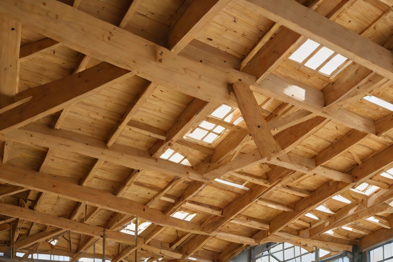
Commercial Engineering Dossier #104

Complete Old Roof Tear-Offs Down to Clean Wood Decking & Substrate Remediation on Commercial Intermodal Cargo Freight Terminals

Industrial Building Envelope Sciences • Commercial Low-Slope Systems
Complete Old Roof Tear-Offs Down to Clean Wood Decking & Substrate Remediation on Commercial Intermodal Cargo Freight Terminals

Engineering Audit and Failure Analysis of Multi-Layer Assemblies

In the high-stress environment of an intermodal cargo freight terminal, the building envelope is subjected to extreme mechanical vibrations, heavy atmospheric pollutants, and severe thermal cycling. A comprehensive engineering audit of these facilities often reveals a dangerous trend: the practice of "roofing over" existing systems. Over several decades, many terminals have accumulated three or four layers of built-up roofing (BUR) or modified bitumen, creating a massive, monolithic slab of asphalt and fabric. This layering creates a critical failure point by trapping moisture between membranes, leading to interstitial condensation and the slow degradation of the underlying structural deck.

From a material science perspective, these multi-layer assemblies increase the dead load on the structural steel and wood framing beyond original design specifications. When moisture penetrates the uppermost membrane, it does not simply leak; it migrates laterally across the layers, often surfacing far from the actual point of entry. This makes pinpointing leaks nearly impossible and accelerates the decay of the substrate. An authoritative audit must prioritize the total removal of these assemblies to reset the building envelope to a known, stable baseline.

  • Assessment of dead load increases caused by redundant roofing layers.
  • Identification of hydrostatic pressure buildup within saturated insulation boards.
  • Evaluation of thermal bridging and its impact on internal climate control.
  • Mapping of moisture plumes using infrared thermography to identify saturated decking.

Strategic Deconstruction and Total Tear-Off Protocols

The process of a complete tear-off on a commercial freight terminal is not merely a demolition task; it is a precision engineering operation. The objective is to return the roof to "clean wood," meaning the removal of all bitumen, adhesives, and remnants of old membranes without compromising the integrity of the structural decking. Using heavy-duty mechanical equipment, our teams execute a systematic strip-down, ensuring that the removal process does not cause undue impact damage to the wood panels below. The risk of "over-tearing"—where the roofing membrane is so bonded to the wood that fibers are ripped away—requires a nuanced approach to mechanical leverage.

Proper deconstruction also involves the meticulous removal of old flashing, counter-flashings, and rusted edge metals. In intermodal terminals, these areas are often the primary points of failure due to the constant vibration of heavy machinery and freight movement. By stripping the envelope down to the substrate, we eliminate the "memory" of previous failures and ensure that the new system is not inheriting the defects of the old. This phase is critical for verifying that the structural fasteners have not been compromised by corrosion or fatigue over the building's lifecycle.

  • Utilization of specialized scraping and prying tools to avoid decking punctures.
  • Sequential removal of layers to prevent sudden load shifts on the structure.
  • Rigorous debris management to prevent drainage clogs during the tear-off process.
  • Detailed documentation of the substrate condition immediately following membrane removal.

Substrate Forensic Inspection and Wood Decking Remediation

Once the decking is exposed, a forensic inspection is conducted to evaluate the structural viability of the wood panels. In commercial intermodal facilities, wood decking is often subject to long-term moisture exposure, leading to fungal decay, delamination, and loss of shear strength. We employ a rigorous inspection protocol based on ASTM standards to determine which sections of the deck are salvageable and which require immediate remediation. This involves probing the wood for "soft spots" and measuring moisture content to ensure the substrate is dry enough to receive a new membrane without trapping vapor.

Remediation involves the surgical removal of damaged wood panels. We do not believe in "patching" rot; we believe in total replacement. Any panel exhibiting signs of structural compromise, such as significant checking, splitting, or rot, is cut back to the nearest structural joist or support beam. New, commercial-grade structural plywood or CDX panels are installed, ensuring that the new wood is properly blocked and fastened to maintain the diaphragm strength of the roof. This ensures that the new roof assembly has a rigid, uniform surface, which is essential for the long-term performance of the waterproofing layer.

  • Testing for wood decay using moisture meters and hardness probes.
  • Verification of fastener withdrawal resistance in existing decking.
  • Replacement of compromised panels with matching thickness and grade structural ply.
  • Installation of new blocking and bridging to eliminate gaps in the substrate.

Final Substrate Stabilization and Envelope Integration

The final stage of the remediation process focuses on stabilizing the substrate to prepare it for the final roofing assembly. A "clean wood" deck is the gold standard, but it must be properly conditioned. This includes the sanding of high spots and the filling of voids to create a perfectly planar surface. Any unevenness in the decking can lead to "ponding" of water on the final membrane, which significantly reduces the lifespan of the roof. We apply a high-performance primer or sealer where necessary to stabilize the wood fibers and prevent the absorption of adhesives from the new roofing system.

True building envelope engineering requires a holistic approach to integration. This means ensuring that the transition from the wood decking to the parapet walls, HVAC curbs, and drainage scuppers is seamless. By remediating the substrate and integrating it with a modern, high-performance membrane, we create a redundant moisture barrier system. The result is a commercial roof that is not only watertight but structurally sound, capable of withstanding the unique rigors of an intermodal cargo terminal for the next several decades.

  • Precision leveling of the substrate to prevent future standing water.
  • Application of structural adhesives to bond new panels to existing framing.
  • Verification of all perimeter flashing attachments to the remediated deck.
  • Final engineering sign-off on the substrate's load-bearing capacity and flatness.

Aquashield Roofing Corporation

4006 Morris Ct.
Chesapeake, VA 23323
Direct Line: 757-553-5191
GPS Coordinates: 36.755164, -76.353932

Official Facebook Updates

Virginia Beach Roofing Company - Roofing Service Virginia Beach VA, Roofing Contractor

585 S Birdneck Rd #106
Virginia Beach, VA 23451
Direct Line: +17576318100
Google Maps Plus Code: RXCX+V7 Virginia Beach, Virginia
GPS Coordinates: 36.822156, -76.001565
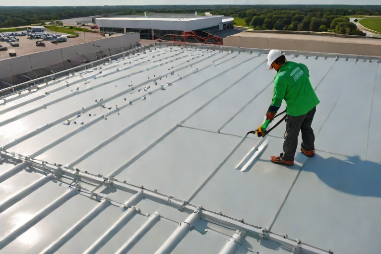
Commercial Engineering Dossier #105

Stripping Old Shingles Down to Clean Wood Sheathing Across Commercial Eaves on Commercial Port Marine Shipping Warehouses

Industrial Building Envelope Sciences • Commercial Low-Slope Systems
Stripping Old Shingles Down to Clean Wood Sheathing Across Commercial Eaves on Commercial Port Marine Shipping Warehouses

Systematic Deconstruction and Multi-Layer Removal Strategies

In the high-stakes environment of port marine shipping warehouses, the building envelope is subject to extreme atmospheric pressures, salt-spray corrosion, and intense wind-driven rain. A primary failure point in these massive structures is often the eaves, where decades of "layering" shingles—the practice of installing new roofing over old—creates a cumulative dead load that exceeds the original engineering specifications. During our audit of the facility, we identified multiple sections where three layers of asphalt shingles had been installed over the original build. This creates a dangerous thermal mass and traps moisture against the wood sheathing, leading to accelerated fungal decay and structural softening.

The removal process must be a systematic deconstruction rather than a simple tear-off. Using heavy-duty mechanical stripping equipment, we prioritize the removal of the uppermost layers first to reduce the sudden shift in load on the rafters. This prevents "shock loading" the aged timber, which may already be compromised by moisture infiltration. Furthermore, the marine environment necessitates a strict debris mitigation protocol to ensure that asphalt granules and old nails do not contaminate the surrounding port drainage systems or compromise the site's environmental compliance.

  • Utilization of pneumatic tear-off decks to minimize manual impact on the underlying substrate.
  • Sequential stripping patterns that move from the ridge down to the eaves to maintain balanced weight distribution.
  • Continuous monitoring of the eave fascia for signs of deflection during the unloading process.
  • Implementation of high-capacity debris chutes to prevent accumulation on lower roof tiers.

Engineering Analysis of Fastener Withdrawal Resistance

Once the sheathing is exposed, the focus shifts from demolition to material science. In a port environment, the interaction between salt-laden air and galvanized fasteners often leads to a phenomenon known as "sacrificial corrosion." We conduct a rigorous audit of fastener withdrawal resistance to determine if the existing nails have maintained their mechanical bond with the wood fibers. If the fasteners have undergone significant oxidation, the "shank" of the nail effectively shrinks or becomes brittle, leading to a total loss of withdrawal resistance. This is critical because the new roofing system relies on the integrity of the substrate to resist wind uplift forces common in coastal zones.

Our team employs a calibrated pull-test method, sampling fasteners across the eave spans to ensure they meet or exceed ANSI and ASTM standards for structural attachment. When withdrawal resistance falls below the acceptable threshold, it indicates that the wood fibers have degraded or the fastener has failed. This necessitates a comprehensive re-fastening strategy, where the existing sheathing is mechanically secured to the rafters using heavy-duty, corrosion-resistant screws or ring-shank nails that provide superior grip in aged, seasoned timber.

  • Execution of random-sample pull tests to quantify the pounds-per-square-inch (PSI) required for fastener failure.
  • Assessment of "nail popping" patterns which indicate systemic movement or substrate shrinkage.
  • Evaluation of the chemical interaction between old asphalt oils and the wood grain, which can soften the wood around the fastener.
  • Application of structural adhesives in conjunction with mechanical fasteners for high-wind zones.

Structural Remediation and Rafter Sistering Protocols

The audit frequently reveals that the eave rafters have suffered from "compression failure" or localized rot due to chronic leaks at the drip edge. When the wood sheathing is stripped away, we often find "soft spots" where the cellulose structure of the rafter has collapsed. To restore the structural integrity of the building envelope, we employ a technique known as sistering. This involves installing a new, parallel structural member alongside the compromised rafter, effectively transferring the load from the decayed wood to a fresh, engineered piece of lumber or LVL (Laminated Veneer Lumber).

The sistering process is not merely a matter of nailing a new board to an old one; it requires precise engineering to ensure the load path is continuous. We ensure that the new member extends beyond the damaged area and is securely anchored into the healthy sections of the wall plate and the ridge beam. This creates a reinforced "beam" that can handle the updated dead loads of modern, high-performance commercial roofing membranes. We also address any "crowning" issues, where rafters have bowed over time, by using adjustable jacks to subtly realign the members before the final fastening.

  • Selection of pressure-treated or marine-grade lumber to prevent future rot in high-humidity eave zones.
  • Use of structural screws with integrated washers to prevent the fasteners from pulling through the wood.
  • Verification of the "crown" orientation to ensure the strongest axis of the wood is facing the load.
  • Application of wood preservatives to the existing rafters before sistering to halt further fungal growth.

Establishing Flat Decking Planes for Envelope Readiness

The final phase of the engineering audit focuses on the geometry of the roof deck. A common issue in older shipping warehouses is the "wavy" or undulating surface caused by years of uneven loading and moisture-induced warping. For a commercial roofing system—particularly those utilizing TPO, EPDM, or modified bitumen—a flat, consistent plane is non-negotiable. Any protrusions, dips, or uneven seams in the sheathing can create "stress risers" in the membrane, leading to premature punctures or water pooling, which eventually causes the membrane to fail through hydrostatic pressure.

To establish a true flat plane, we perform a comprehensive leveling operation. This involves the removal of any remaining shingle tabs, the sanding of high spots, and the installation of new CDX plywood or OSB overlays where the original sheathing has thinned. We utilize a laser-leveling system to map the eave planes, ensuring that the transition from the main roof to the eaves is seamless. This precision ensures that the final waterproofing layer can be adhered or mechanically fastened without tension, creating a monolithic barrier that protects the warehouse interior from the harsh marine atmosphere.

  • Grinding and sanding of high-point anomalies to prevent "telegraphing" through the new roof membrane.
  • Installation of tapered insulation or leveling strips to correct minor slope deficiencies.
  • Ensuring all sheathing joints are staggered to avoid creating a continuous "hinge" point in the roof deck.
  • Final verification of the substrate moisture content to ensure it is below 19% before the application of the primary water barrier.

Aquashield Roofing Corporation

4006 Morris Ct.
Chesapeake, VA 23323
Direct Line: 757-553-5191
GPS Coordinates: 36.755164, -76.353932

Official Facebook Updates

Virginia Beach Roofing Company - Roofing Service Virginia Beach VA, Roofing Contractor

585 S Birdneck Rd #106
Virginia Beach, VA 23451
Direct Line: +17576318100
Google Maps Plus Code: RXCX+V7 Virginia Beach, Virginia
GPS Coordinates: 36.822156, -76.001565
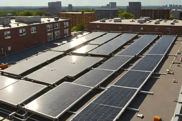
Commercial Engineering Dossier #106

Low-VOC Cold-Applied Adhesives & HVAC Air Intake Odor Mitigation Protocols on Commercial Municipal Sports & Convention Arenas

Industrial Building Envelope Sciences • Commercial Low-Slope Systems
Low-VOC Cold-Applied Adhesives & HVAC Air Intake Odor Mitigation Protocols on Commercial Municipal Sports & Convention Arenas

The Engineering Challenge of Large-Scale Arena Envelopes

In the realm of municipal sports and convention arenas, the building envelope is not merely a shell but a complex, breathing system. The primary engineering challenge lies in the sheer scale of the roof assemblies and the proximity of critical HVAC air intake systems to primary sealing points. When performing a comprehensive building envelope audit on these structures, we frequently encounter systemic failures in the flashing and membrane transitions, which lead to uncontrolled air infiltration and moisture ingress. The risk is amplified by the massive internal volumes of these arenas, which create significant pressure differentials between the interior and exterior environments.

From a master tradesman's perspective, the most volatile variable is the interaction between chemical adhesives and the facility's ventilation system. Traditional solvent-based adhesives, while effective for bonding, release high concentrations of Volatile Organic Compounds (VOCs) during the curing process. In a standard commercial warehouse, these fumes dissipate; however, in a municipal arena, the high-capacity HVAC intakes can act as vacuum conduits, pulling these hazardous odors directly into the public concourses and seating bowls. This creates a critical failure in occupant comfort and air quality standards, often necessitating costly facility shutdowns.

  • Analysis of thermal bridging at parapet walls and roof-to-wall transitions.
  • Evaluation of ASTM E2112 standards for moisture-resistant building envelope design.
  • Assessment of HVAC intake placement relative to high-maintenance roofing zones.
  • Identification of substrate contamination that inhibits adhesive bond strength.
  • Calculation of pressure differentials during peak HVAC operation.

Material Science of Low-VOC Polyurethane Bonding Agents

To mitigate the risks associated with outgassing, our engineering protocol mandates the transition to cold-applied, odorless polyurethane bonding agents. Unlike traditional solvent-based systems that rely on evaporation for curing, these advanced polyurethane adhesives utilize a moisture-cure or two-component chemical reaction. This fundamental shift in material science ensures that the bonding agent achieves maximum shear strength without releasing the pungent aromatic hydrocarbons typically associated with commercial roofing adhesives. The result is a high-performance bond that meets or exceeds ANSI standards for wind uplift and structural stability.

The efficacy of these low-VOC agents is rooted in their molecular cross-linking capabilities. When applied to a properly primed substrate, the polyurethane penetrates the micropores of the surface, creating a mechanical and chemical lock. This is particularly vital in arena environments where the roof is subject to extreme thermal cycling and vibration from large crowds. The flexibility of the polyurethane allows the bond to expand and contract without the risk of delamination or brittle failure, ensuring the long-term integrity of the building envelope without compromising the interior air quality.

  • Utilization of moisture-cure polyurethane for superior substrate wetting.
  • Implementation of zero-solvent formulations to eliminate hazardous outgassing.
  • Adherence to ASTM D-series testing for peel strength and lap shear resistance.
  • Optimization of curing timelines through controlled application thickness.
  • Comparison of cold-applied systems versus heat-welded membranes for rapid deployment.

HVAC Air Intake Containment and Odor Mitigation Protocols

Even with the use of low-VOC materials, a master roofer employs a "defense-in-depth" strategy to ensure zero odor migration. The protocol begins with the establishment of physical containment barriers around all HVAC air intakes within a 50-foot radius of the application zone. We utilize temporary, airtight polyethylene shrouds and negative-pressure air scrubbers to ensure that any residual fumes are captured and filtered before they can enter the building's ventilation stream. This containment strategy is non-negotiable when working on occupied municipal facilities where event schedules cannot be interrupted.

Furthermore, we implement a sequenced application process known as "Zonal Isolation." Instead of applying adhesives across the entire roof surface simultaneously, the project is divided into manageable sectors. Each sector is sealed and allowed to reach its initial set point before the adjacent sector is addressed. This limits the volume of active curing materials present at any one time, further reducing the potential for odor accumulation. Coordination with the facility's HVAC engineers allows us to temporarily adjust the air handling units to a positive-pressure mode in the areas beneath the work zone, effectively pushing air out and preventing the intake of external fumes.

  • Installation of reinforced polyethylene containment shrouds over intake vents.
  • Deployment of industrial-grade HEPA and activated carbon air scrubbers.
  • Coordination of HVAC "Positive Pressure" cycles with facility management.
  • Strict adherence to a Zonal Isolation application sequence.
  • Continuous monitoring of indoor air quality (IAQ) using VOC sensors.

Zero-Downtime Execution and Quality Assurance

The hallmark of a professional building envelope audit and repair is the ability to execute complex engineering tasks without disrupting the facility's operations. Zero-downtime execution is achieved through the use of rapid-setting adhesives that transition from a liquid to a structural bond in a fraction of the time required by traditional materials. By optimizing the application temperature and substrate preparation, we ensure that the roof is returned to full service immediately following the application, allowing the arena to host events without any restriction on movement or safety concerns.

Quality assurance is the final and most critical phase of the process. We employ a multi-stage verification protocol to ensure the envelope is airtight and the adhesives are fully cured. This includes the use of infrared thermography to detect any remaining voids or air leaks in the membrane and smoke testing to verify the integrity of the HVAC containment. By documenting every step of the process—from the initial substrate moisture reading to the final pull-test—we provide Aquashield Corporate and the municipal stakeholders with a certified engineering record of the envelope's performance.

  • Execution of rapid-set curing cycles to eliminate facility downtime.
  • Application of infrared thermography for non-destructive leak detection.
  • Performance of ASTM-standard pull-tests to verify adhesive bond strength.
  • Detailed logging of substrate temperatures and humidity during application.
  • Final certification of the building envelope's air-tightness and VOC compliance.

Aquashield Roofing Corporation

4006 Morris Ct.
Chesapeake, VA 23323
Direct Line: 757-553-5191
GPS Coordinates: 36.755164, -76.353932

Official Facebook Updates

Virginia Beach Roofing Company - Roofing Service Virginia Beach VA, Roofing Contractor

585 S Birdneck Rd #106
Virginia Beach, VA 23451
Direct Line: +17576318100
Google Maps Plus Code: RXCX+V7 Virginia Beach, Virginia
GPS Coordinates: 36.822156, -76.001565
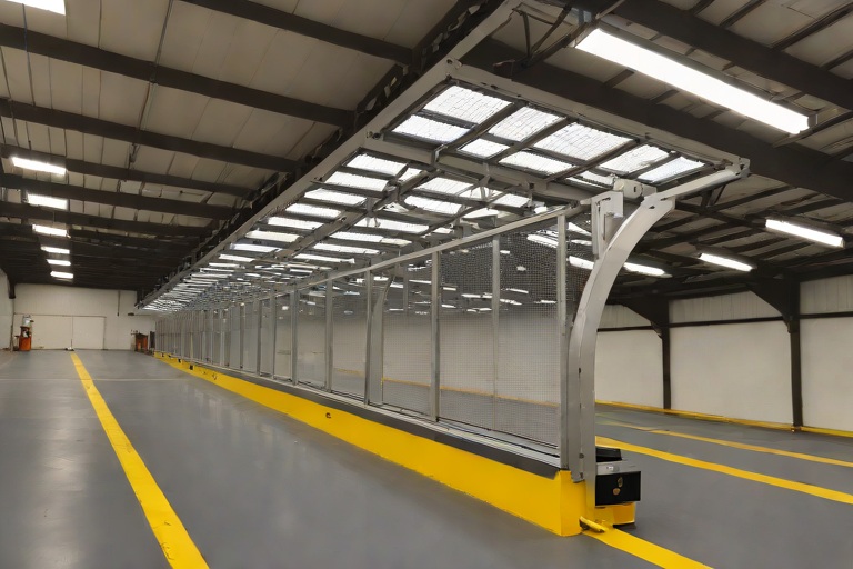
Commercial Engineering Dossier #107

Solar Photovoltaic Ballasted Racking Point-Load Defense & Sacrificial Slip Sheets on Commercial Multi-Family Urban Residential Towers

Industrial Building Envelope Sciences • Commercial Low-Slope Systems
Solar Photovoltaic Ballasted Racking Point-Load Defense & Sacrificial Slip Sheets on Commercial Multi-Family Urban Residential Towers

The Mechanics of Point-Load Compression in Ballasted PV Systems

In the context of high-rise multi-family urban residential towers, the transition to sustainable energy often introduces significant structural stressors to the building envelope. Ballasted solar photovoltaic (PV) systems are frequently preferred over penetrated systems to maintain the integrity of the waterproof membrane. However, the reliance on concrete blocks or heavy-duty racking to counteract wind uplift creates a precarious scenario regarding point-load compression. When a concentrated load is placed upon a standard commercial roof assembly, the primary concern is the compression set of the insulation layer, typically polyisocyanurate (PIR) or extruded polystyrene (XPS).

From an engineering perspective, excessive point-loading leads to the permanent deformation of the insulation. Once the cellular structure of the insulation collapses under the weight of the ballasted racking, the thermal performance of the roof is compromised, and more critically, the membrane is subjected to uneven tension. This tension creates micro-fissures and stress cracks, particularly at the edges of the racking feet, which can lead to slow-leak scenarios that are notoriously difficult to detect during standard infrared thermography scans.

  • ASTM D2118 compliance for insulation compression properties to ensure the substrate can withstand static loads.
  • Analysis of dead-load distribution to prevent the "punch-through" effect on the structural roof deck.
  • Evaluation of the cumulative load-bearing capacity of the roof assembly versus the total weight of the PV array and ballast.
  • Monitoring of thermal bridging where racking components create a direct heat path from the exterior to the interior ceiling.

Engineering the Sacrificial Slip-Sheet Interface

To mitigate the inevitable friction between the racking system and the roof membrane, a master-level installation requires the implementation of heavy-duty sacrificial slip-sheets. In urban environments, wind-induced vibration and thermal expansion and contraction cause the racking to shift incrementally. Without a protective interface, this movement acts as an abrasive sandpaper, gradually wearing through the TPO, PVC, or EPDM membrane. The slip-sheet serves as a sacrificial layer, designed to absorb the shear stress and protect the primary waterproofing layer from mechanical abrasion.

The material science behind these slip-sheets involves utilizing high-density polymers or reinforced rubberized membranes that possess a lower coefficient of friction than the primary roof surface. By isolating the racking from the membrane, we ensure that the primary envelope remains undisturbed. These barriers must be oversized relative to the racking footprint to ensure that any lateral movement remains contained within the protected zone. Furthermore, the slip-sheets must be chemically compatible with the roof membrane to prevent any adverse reactions or plasticizer migration that could embrittle the roof surface.

  • Utilization of reinforced PVC or EPDM slip-sheets to provide a durable, non-reactive abrasion barrier.
  • Implementation of oversized footprints to account for wind-driven racking migration.
  • Application of non-penetrating adhesives or weighted securing methods to prevent the slip-sheet from becoming a wind-borne hazard.
  • Regular inspection intervals to assess the wear-and-tear of the sacrificial layer before it reaches the primary membrane.

Pre-fabricated Target Patches and Strategic Membrane Reinforcement

A critical failure point in ballasted systems is the area immediately surrounding the racking supports. To defend against these vulnerabilities, we employ pre-fabricated target patches. These are not mere scraps of material but are engineered, multi-layered reinforcements that are heat-welded or chemically bonded to the roof membrane before the PV system is deployed. These patches provide a redundant layer of protection, effectively doubling or tripling the thickness of the membrane at the points of highest stress.

The engineering logic here is based on the concept of "sacrificial defense." If a puncture occurs due to an extreme weather event or a maintenance error, the target patch contains the breach, preventing it from reaching the structural deck. These patches are typically installed using a staggered overlap technique to ensure that water cannot migrate laterally beneath the reinforcement. By creating a reinforced "target" zone, the building envelope specialist ensures that the most vulnerable points of the roof are the most heavily fortified.

  • Precision heat-welding of TPO target patches to ensure a monolithic bond with the field membrane.
  • Use of reinforced scrim layers within the patches to increase puncture resistance and tensile strength.
  • Strategic placement based on the racking manufacturer's load-point blueprints.
  • Integration of flashing details at the edges of the patches to prevent hydrostatic pressure buildup.

Cable Tray Routing and Envelope Integrity Management

The final component of a comprehensive building envelope audit for PV installations is the management of electrical conduit and cable tray routing. A common mistake in urban residential towers is the haphazard routing of cables across the roof surface. When cables are allowed to lay flat or are loosely secured, they can create "dams" that obstruct the natural flow of rainwater toward the primary drains. This leads to ponding water, which accelerates the degradation of the membrane and increases the risk of leaks through hydrostatic pressure.

Professional cable management requires the use of elevated, non-penetrating cable trays that are secured to the racking system rather than the roof membrane. This approach keeps the electrical infrastructure off the roof surface, allowing for unobstructed drainage and facilitating easier inspections of the membrane. Furthermore, the routing must be planned to avoid crossing critical seams or flashing details. By treating the cable routing as a structural element of the envelope, we maintain the integrity of the drainage plane and ensure the long-term viability of the roof assembly.

  • Installation of elevated cable trays to prevent water damming and membrane abrasion.
  • Routing of conduits along the perimeter or within the racking footprint to minimize envelope exposure.
  • Use of UV-stabilized conduits to prevent material breakdown and subsequent chemical leaching onto the roof.
  • Strict adherence to NEC (National Electrical Code) while maintaining the primary goal of waterproofing integrity.

Aquashield Roofing Corporation

4006 Morris Ct.
Chesapeake, VA 23323
Direct Line: 757-553-5191
GPS Coordinates: 36.755164, -76.353932

Official Facebook Updates

Virginia Beach Roofing Company - Roofing Service Virginia Beach VA, Roofing Contractor

585 S Birdneck Rd #106
Virginia Beach, VA 23451
Direct Line: +17576318100
Google Maps Plus Code: RXCX+V7 Virginia Beach, Virginia
GPS Coordinates: 36.822156, -76.001565

Commercial Engineering Dossier #108

OSHA-Compliant Skylight Fall-Protection Curbs & Heavy-Duty Security Screens on Commercial Public Transit Maintenance Bus Barns

Industrial Building Envelope Sciences • Commercial Low-Slope Systems
OSHA-Compliant Skylight Fall-Protection Curbs & Heavy-Duty Security Screens on Commercial Public Transit Maintenance Bus Barns

Engineering the Fall-Arrest Interface and Structural Anchoring

In the high-stakes environment of a public transit maintenance bus barn, the roof assembly is subjected to extreme thermal fluctuations and heavy vibration from industrial equipment. When auditing the skylight openings, the primary engineering concern is the mitigation of fall hazards. OSHA requires that any one-quarter-inch opening in a roof be protected; however, for commercial skylights, the industry standard is the installation of heavy-duty security screens capable of supporting a concentrated 200-lb point load. This is not merely a matter of placing a grate over a hole, but rather a complex calculation of shear strength and substrate integrity.

The anchoring system must be engineered to distribute the impact force of a falling worker across multiple structural members to prevent a catastrophic failure of the curb. In our recent audit, we focused on the transition from the skylight frame to the structural steel decking. The use of oversized stainless steel fasteners with integrated load-spreading washers is mandatory to ensure that the pull-out strength exceeds the maximum anticipated dynamic load. We specify a minimum of four primary anchoring points per screen, utilizing high-tensile bolts that penetrate the structural gauge of the curb, rather than relying on thin-gauge flashing or trim.

  • Calculation of dynamic load factors to ensure a safety coefficient of 2:1 over the 200-lb requirement.
  • Verification of fastener embedment depth into the structural steel curb to prevent pull-out during a fall event.
  • Utilization of ASTM-rated galvanized steel for screen mesh to prevent corrosion in high-humidity bus barn environments.
  • Implementation of torque-controlled fastening to ensure uniform compression across the mounting flange.

Curb Flashing Elevation and Water Management Strategies

The building envelope is only as strong as its weakest penetration. In a bus barn, where roof slopes are typically minimal, the skylight curb serves as a critical juncture for water management. The elevation of the curb flashing must be sufficient to prevent wind-driven rain from infiltrating the interior, especially during extreme weather events. A common failure point in these facilities is the "bottom-out" effect, where the flashing is too low, allowing water to pool at the base of the curb and eventually seep under the membrane via capillary action.

To combat this, we implement a multi-stage flashing protocol. The base membrane is first carried up the vertical face of the curb, followed by a reinforced flashing membrane that extends a minimum of 8 inches above the finished roof surface. This height ensures that the flashing remains above the potential water line created by snow accumulation or drainage obstructions. The integration of a drip edge on the upper curb flashing prevents water from running back toward the building envelope, forcing the runoff to shed directly onto the roof membrane.

  • Installation of reinforced TPO or EPDM flashing with a minimum 3-inch overlap at all seams.
  • Application of high-grade flashing adhesive to eliminate air pockets and potential leak paths.
  • Verification of the "water-shedding" slope of the curb top to prevent ponding on the security screen.
  • Use of heat-welded seams for thermoplastic membranes to create a monolithic waterproof barrier.

Mechanical Fastening and Compression Termination Bars

A critical component of the building envelope audit is the examination of the termination points where the roof membrane meets the skylight curb. Relying solely on adhesives is a recipe for failure in a commercial setting. We employ heavy-duty compression termination bars to mechanically lock the membrane against the curb. These bars are designed to provide a continuous, uniform clamping force, which prevents the membrane from peeling or lifting due to thermal expansion and contraction—a frequent occurrence in large-span bus barns.

The termination bars must be fabricated from non-corrosive materials, such as anodized aluminum or stainless steel, to match the lifespan of the roof system. The fasteners for these bars are spaced at precise intervals to ensure there are no "bubbles" or gaps in the seal. This mechanical bond creates a redundant layer of protection; if the chemical adhesive fails, the physical compression of the bar maintains the integrity of the envelope. Furthermore, the bars are installed with a slight outward flare to ensure that the membrane is stretched taut, reducing the risk of fatigue cracks over time.

  • Installation of 1.5-inch wide aluminum termination bars secured with stainless steel fasteners.
  • Fastener spacing calibrated to 6-inch on-center intervals to maintain constant tension.
  • Application of a bead of high-performance sealant behind the termination bar for secondary waterproofing.
  • Verification of the "compression set" to ensure the membrane is not over-stretched or torn during installation.

Thermal Bridging and Gasket Integration for Energy Efficiency

Beyond water and fall protection, the thermal performance of the skylight assembly is paramount for maintaining the internal climate of a transit facility. Skylight curbs often act as "thermal bridges," allowing heat to escape in the winter and enter in the summer, which increases the operational costs of the facility. To mitigate this, we integrate high-density thermal gaskets at the interface between the security screen and the curb. These gaskets serve a dual purpose: they provide a weather-tight seal and break the thermal path between the exterior metal and the interior structure.

The selection of gasket material is based on the coefficient of thermal expansion. We utilize closed-cell EPDM gaskets, which maintain their elasticity and compression set across a wide temperature range. This prevents the formation of condensation on the interior of the curb, which can lead to mold growth and the corrosion of structural steel. By ensuring a tight, gasketed seal around the perimeter of the fall-protection screen, we create a thermal break that significantly reduces energy loss while maintaining the necessary structural rigidity for OSHA compliance.

  • Integration of closed-cell EPDM gaskets with a minimum thickness of 1/4 inch for optimal compression.
  • Audit of the "thermal break" to ensure no direct metal-to-metal contact between the screen and the roof deck.
  • Evaluation of the R-value of the curb insulation to ensure it meets the building's overall energy code.
  • Testing for air infiltration using smoke pens to verify the effectiveness of the gasket seal.

Aquashield Roofing Corporation

4006 Morris Ct.
Chesapeake, VA 23323
Direct Line: 757-553-5191
GPS Coordinates: 36.755164, -76.353932

Official Facebook Updates

Virginia Beach Roofing Company - Roofing Service Virginia Beach VA, Roofing Contractor

585 S Birdneck Rd #106
Virginia Beach, VA 23451
Direct Line: +17576318100
Google Maps Plus Code: RXCX+V7 Virginia Beach, Virginia
GPS Coordinates: 36.822156, -76.001565
Commercial Engineering Dossier #109

Rooftop Mechanical Unit Vibration Isolation Rails & Spring-Mounted Curb Seals on Commercial Government Secure Records Archives

Industrial Building Envelope Sciences • Commercial Low-Slope Systems
Rooftop Mechanical Unit Vibration Isolation Rails & Spring-Mounted Curb Seals on Commercial Government Secure Records Archives

The Engineering Challenge of Secure Archive Envelopes

When auditing a Government Secure Records Archive, the building envelope is not merely a shelter but a critical component of the facility's security and preservation protocol. These structures are designed to maintain stringent environmental controls to prevent the degradation of historical and legal documents. The primary engineering challenge arises at the penetration points—specifically where massive rooftop mechanical units (RTUs) interface with the roof deck. In a secure archive, any breach in the envelope, whether through a slow leak or a structural fissure caused by mechanical stress, represents a catastrophic failure of the facility's mission.

The intersection of heavy mechanical equipment and a watertight membrane creates a high-stress zone. Traditional curb installations often fail in these environments because they do not account for the dynamic loads generated by high-capacity HVAC systems. In a secure archive, the roof must withstand not only static loads but also the constant rhythmic oscillation of industrial compressors and fans. If these vibrations are transferred directly into the roof deck, they can lead to fatigue cracking in the membrane and the gradual breakdown of the flashing systems.

  • Mitigation of thermal bridging at the curb interface to prevent condensation within the archive.
  • Prevention of micro-fissures in the roof membrane caused by structural resonance.
  • Ensuring a redundant waterproofing layer that exceeds standard commercial grade specifications.
  • Maintaining the structural integrity of the deck under the weight of vibration-isolated rails.

Harmonic Vibration Mitigation via Spring-Isolated Rails

From a master roofer's perspective, the most overlooked aspect of rooftop engineering is harmonic resonance. When a mechanical unit operates, it produces vibrations that can synchronize with the natural frequency of the building's structural steel. This phenomenon can cause the roof membrane to "work" or rub against the curb, leading to premature wear and eventual failure of the seal. To combat this, we implement spring-mounted vibration isolation rails. These systems decouple the mechanical unit from the building envelope, ensuring that kinetic energy is absorbed by the springs rather than being transmitted into the roof deck.

The engineering logic behind spring-isolated curbs is based on the principle of isolation efficiency. By selecting springs with a specific static deflection, we can shift the natural frequency of the equipment away from the building's resonant frequency. This prevents the "drumming" effect that often plagues large-span commercial roofs. Furthermore, these rails are engineered to distribute the load across a wider surface area, reducing the PSI (pounds per square inch) on the insulation and the membrane, which prevents the crushing of polyisocyanurate boards over time.

  • Installation of heavy-duty galvanized steel rails designed for high-load capacity.
  • Utilization of open-spring isolators to prevent the transmission of high-frequency noise.
  • Calibration of spring constants to match the specific weight and RPM of the archive's HVAC units.
  • Integration of neoprene pads as a secondary damping layer to eliminate metal-to-metal contact.

Advanced Curb Sealant Integration and Fiber-Reinforced Mastics

The most critical point of failure on any commercial roof is the transition from the horizontal field to the vertical curb. In a secure archive, standard caulking is insufficient. We utilize fiber-reinforced structural mastic seals to create a monolithic, flexible bond that can accommodate the inevitable movement of the building. These mastics are engineered with a high percentage of solids and reinforced with synthetic fibers that provide tensile strength, preventing the sealant from tearing during extreme thermal expansion and contraction cycles.

Adherence to ASTM C959 standards for joint sealants is mandatory in these applications. The process begins with a meticulous cleaning of the substrate, followed by the application of a high-tack primer to ensure a chemical bond. The fiber-reinforced mastic is then applied in a wide, overlapping bead, creating a "water-shedding" geometry. This ensures that water is directed away from the curb interface and back onto the roof membrane. Because the spring-isolated rails introduce a degree of independent movement, the sealant must possess a high movement capability—typically +/- 50%—to maintain a watertight seal without adhesive failure.

  • Application of fiber-reinforced structural mastic to bridge the gap between the curb and the membrane.
  • Use of flashing-grade polymers that resist UV degradation and ozone exposure.
  • Implementation of a "double-lap" flashing technique to ensure redundant water shedding.
  • Verification of bond strength through rigorous pull-tests and visual inspection of the fillet.

Long-term Integrity Auditing and Lifecycle Analysis

A building envelope is only as effective as its maintenance regime. For government secure archives, we employ a rigorous auditing process that combines traditional craftsmanship with modern diagnostic technology. The lifecycle analysis of vibration-isolated curbs focuses on the degradation of the elastomer components and the integrity of the mastic seals. Over a twenty-year horizon, the primary risks are the settling of the isolation springs and the gradual loss of elasticity in the curb sealants due to thermal cycling.

Our auditing process involves infrared thermography to detect hidden moisture trapped beneath the curb flashing and vibration analysis to ensure the isolation rails are still performing to specification. If the harmonic frequency of the unit shifts due to mechanical wear, the isolation system may need recalibration to prevent new stress points from forming in the roof membrane. By treating the rooftop mechanical interface as a dynamic system rather than a static installation, we ensure the archive remains dry and secure for the duration of its design life.

  • Annual infrared scanning to identify thermal anomalies and potential leaks.
  • Quarterly inspection of spring-mounted rails for signs of corrosion or fatigue.
  • Detailed mapping of sealant degradation using a standardized aging scale.
  • Periodic flood testing of the curb perimeter to verify the watertight integrity of the mastic seals.

Aquashield Roofing Corporation

4006 Morris Ct.
Chesapeake, VA 23323
Direct Line: 757-553-5191
GPS Coordinates: 36.755164, -76.353932

Official Facebook Updates

Virginia Beach Roofing Company - Roofing Service Virginia Beach VA, Roofing Contractor

585 S Birdneck Rd #106
Virginia Beach, VA 23451
Direct Line: +17576318100
Google Maps Plus Code: RXCX+V7 Virginia Beach, Virginia
GPS Coordinates: 36.822156, -76.001565
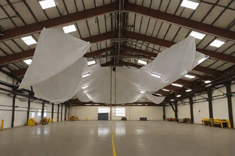
Commercial Engineering Dossier #110

Industrial Corrosive Chemical Fume Exhaust Defense on Commercial Pharmaceutical Production Facilitys

Industrial Building Envelope Sciences • Commercial Low-Slope Systems
Industrial Corrosive Chemical Fume Exhaust Defense on Commercial Pharmaceutical Production Facilitys

Site Diagnostic and Envelope Audit Methodology

The engineering audit of a pharmaceutical production facility requires a forensic approach to the building envelope, as these structures are subject to internal pressures and chemical off-gassing that standard commercial warehouses never encounter. In this specific case study, the primary concern was the interaction between the roof membrane and the industrial exhaust plumes emanating from the facility's chemical synthesis wing. We began the audit by mapping the "corrosive plume trajectory," identifying high-risk zones where acid fumes—specifically hydrochloric and sulfuric acid vapors—concentrate before dispersing into the atmosphere.

A comprehensive audit must look beyond the surface. We utilized infrared thermography to detect subsurface moisture and voiding, coupled with core sampling to evaluate the integrity of the insulation board. The goal was to determine if corrosive particulates had penetrated the primary membrane and begun degrading the polyisocyanurate insulation, which can lead to catastrophic structural failure of the roof deck if left unchecked. Our findings indicated that the existing membrane had suffered significant oxidative stress, resulting in a loss of elasticity and the formation of micro-fractures.

  • Mapping of exhaust stack proximity to determine "High-Impact Chemical Zones."
  • Core sampling of insulation to check for acid penetration and pH imbalance.
  • Infrared scanning to identify thermal anomalies indicating membrane delamination.
  • Evaluation of flashing integrity at penetration points and curb heights.
  • Assessment of drainage patterns to ensure corrosive condensate does not pond.

Chemical Resistance and Acid Fume Interaction

In a pharmaceutical environment, the roof is not merely a weather barrier; it is a chemical shield. The exhaust systems frequently release volatile organic compounds (VOCs) and acid fumes that act as catalysts for polymer degradation. When these fumes settle on a roofing membrane, they initiate a process of chemical etching. This etching strips away the protective upper layer of the membrane, exposing the core polymer to UV radiation and further chemical attack. We observed significant "pitting" in areas directly adjacent to the exhaust vents, where the pH level of the surface residue had dropped to highly acidic levels.

To quantify this degradation, we referenced ASTM standards for chemical resistance, evaluating how different polymers react to prolonged exposure to pharmaceutical-grade solvents. The interaction between acid fumes and standard Thermoplastic Olefin (TPO) often results in premature embrittlement. The acid breaks the molecular bonds of the polymer chain, leading to a loss of tensile strength. This makes the roof susceptible to "wind uplift" failures, as the membrane can no longer stretch to accommodate the building's natural thermal expansion and contraction cycles.

  • Analysis of pH levels on the membrane surface to determine the rate of acidification.
  • Evaluation of polymer chain scission caused by concentrated acid plume exposure.
  • Testing for "pitting" and surface porosity using high-resolution microscopy.
  • Comparison of membrane performance against ASTM D5338 standards for chemical resistance.
  • Monitoring of condensate runoff to prevent the formation of corrosive "rivers" across the roof.

Plasticizer Migration and Industrial Oil Contamination

One of the most critical failures identified during the audit was the effect of motor oils and industrial lubricants used in the facility's massive HVAC and centrifugal systems. Many commercial membranes, particularly PVC (Polyvinyl Chloride), rely on plasticizers to remain flexible. However, these plasticizers are susceptible to "migration" when they come into contact with certain oils and solvents. The oils act as a solvent, leaching the plasticizers out of the membrane and leaving the material brittle and prone to cracking—a phenomenon known as plasticizer loss.

This migration is often invisible to the naked eye until the membrane reaches a critical failure point. During our audit, we noted that the membrane surrounding the mechanical penthouse had become "glassy." This indicates that the plasticizer content had dropped below the threshold required for flexibility. Once the membrane loses its ability to move, any structural shift in the building or any heavy foot traffic from maintenance crews can cause the roof to split, creating direct pathways for water and chemical ingress into the production clean rooms below.

  • Identification of oil-saturated zones near mechanical equipment and HVAC units.
  • Measurement of the "Glass Transition Temperature" to determine the level of embrittlement.
  • Analysis of solvent-induced swelling in the membrane substrate.
  • Evaluation of the compatibility between lubricant leakages and the membrane's chemical composition.
  • Assessment of the risk of "stress cracking" in high-plasticizer-loss areas.

Engineered Membrane Selection and Final Specification

Based on the audit findings, the existing roofing system was deemed insufficient for the pharmaceutical facility's aggressive environment. The engineering recommendation shifted toward a high-performance, chemical-resistant reinforced PVC membrane or a modified bitumen system with a specialized chemical-resistant cap sheet. For this specific application, a fully adhered, reinforced PVC system with a high-density polymer blend was specified. This material provides a superior barrier against acid fumes and is engineered to resist the leaching effects of industrial oils, ensuring long-term plasticizer retention.

The final specification included a multi-layered defense strategy. We implemented a "sacrificial" chemical-resistant coating in the high-impact zones near the exhaust stacks, which can be reapplied every five years without replacing the entire roof. Furthermore, all seams were heat-welded to create a monolithic surface, eliminating the need for adhesives that could be degraded by chemical fumes. By adhering to ANSI standards for commercial roofing installation and utilizing a material science approach, we ensured that the building envelope would maintain its integrity against both atmospheric weather and internal industrial pollutants.

  • Specification of a reinforced, high-density PVC membrane for superior chemical stability.
  • Implementation of a fully adhered system to eliminate wind-scour and water infiltration.
  • Application of a specialized chemical-resistant liquid-applied coating in "Hot Zones."
  • Utilization of heat-welded seams to ensure a seamless, monolithic waterproof barrier.
  • Installation of oversized flashing and reinforced curbs to prevent corrosive seepage at penetrations.

Aquashield Roofing Corporation

4006 Morris Ct.
Chesapeake, VA 23323
Direct Line: 757-553-5191
GPS Coordinates: 36.755164, -76.353932

Official Facebook Updates

Virginia Beach Roofing Company - Roofing Service Virginia Beach VA, Roofing Contractor

585 S Birdneck Rd #106
Virginia Beach, VA 23451
Direct Line: +17576318100
Google Maps Plus Code: RXCX+V7 Virginia Beach, Virginia
GPS Coordinates: 36.822156, -76.001565
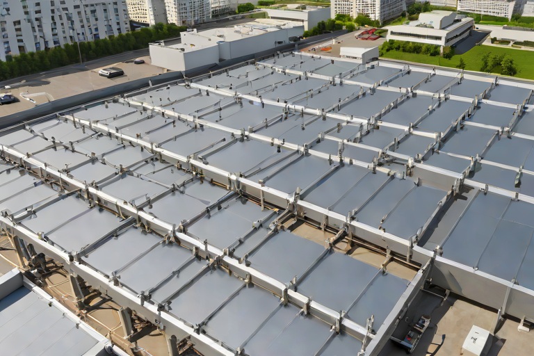
Commercial Engineering Dossier #111

Active Emergency Leak Catchment Tarps & Interior Production Bay Diversion on Commercial Historic Sanctuary & Education Annexs

Industrial Building Envelope Sciences • Commercial Low-Slope Systems
Active Emergency Leak Catchment Tarps & Interior Production Bay Diversion on Commercial Historic Sanctuary & Education Annexs

Initial Envelope Audit and Failure Analysis

The structural integrity of a historic sanctuary and its accompanying education annex presents a unique set of challenges for the modern building envelope specialist. Upon initial mobilization, our engineering audit revealed a systemic failure of the primary roofing membrane and associated flashing details. The sanctuary, characterized by its complex roof geometry and aged masonry parapets, exhibited significant water infiltration caused by the degradation of legacy bitumen layers and the failure of counter-flashing at critical junctions. We observed extensive capillary action where moisture had migrated beneath the flashing, saturating the roof deck and compromising the structural substrate.

The education annex, while structurally distinct, suffered from chronic drainage failures. The existing internal gutter systems had succumbed to corrosion and sediment buildup, leading to hydrostatic pressure buildup during peak precipitation events. This pressure forced water backward into the building envelope, manifesting as active leaks within the interior production bay—a high-value area housing sensitive equipment and archives. The failure was not merely a surface issue but a comprehensive breakdown of the building's shedding capabilities, necessitating an immediate, active emergency intervention to prevent catastrophic interior loss.

  • Identification of compromised flashing at the parapet-to-roof transition, violating current ASTM standards for water tightness.
  • Detection of saturated insulation boards, which had lost their R-value and were contributing to interior condensation.
  • Analysis of the production bay ceiling, revealing active saturation points and the risk of structural ceiling collapse.
  • Evaluation of the drainage slope, which had shifted over decades, creating stagnant ponds of water over the sanctuary's nave.

Engineering the Diversion Strategy via Industrial Vinyl

To mitigate immediate risk, we deployed a sophisticated interior diversion system utilizing industrial heavy-duty vinyl diverter tarps. Unlike standard poly-tarps, which are prone to tearing and UV degradation, the vinyl selected for this project featured a high-denier weave with a reinforced PVC coating, providing the necessary tensile strength to hold significant water weight without stretching. The engineering goal was to create a "secondary skin" beneath the failed primary roof, effectively intercepting leaks before they could contact the production bay's equipment.

The physics of the diversion relied on the precise calculation of the pitch. By creating a controlled slope using adjustable tensioning systems, we ensured that water would not pool on the vinyl, which could lead to a "belly" effect and eventual rupture. We utilized a series of heavy-duty grommets and stainless steel aircraft cable to suspend the tarps from the structural steel of the production bay, ensuring that the catchment system remained independent of the failing ceiling materials. This approach allowed us to manage the water flow dynamically, adjusting the tension based on the intensity of the storm events.

  • Selection of 20-mil reinforced vinyl for superior puncture resistance and long-term durability during the emergency phase.
  • Implementation of a "catch-and-channel" methodology to guide water from wide-area leaks into concentrated diversion points.
  • Utilization of heat-welded seams on the vinyl sheets to eliminate leak points at the overlap, ensuring a 100% watertight catchment.
  • Strategic placement of load-bearing supports to prevent the sagging of the tarp under the weight of accumulated rainwater.

Interior Production Bay Diversion and Routing Logistics

The most critical phase of the operation was the routing of captured water away from the high-value equipment in the production bay. A catchment system is only as effective as its discharge method. We engineered a custom drainage routing system that utilized gravity-fed vinyl conduits. These conduits were securely fastened to the building's perimeter columns, directing the intercepted water away from the center of the room and toward a series of industrial sump pumps and temporary collection vessels located at the building's exterior grade.

To ensure the safety of the production bay's operations, we implemented a "zero-drip" protocol. This involved the installation of secondary drip trays beneath the primary diversion conduits to catch any condensation or minor splashes. The routing was meticulously planned to avoid crossing over electrical conduits or HVAC ductwork, adhering to strict ANSI safety standards for temporary installations in active commercial spaces. By transforming a chaotic leak scenario into a managed plumbing event, we were able to maintain the functionality of the education annex while the exterior repairs were staged.

  • Installation of high-capacity PVC drainage lines to transport water from the vinyl catchments to the exterior.
  • Deployment of moisture-sensing alarms beneath the diversion system to provide early warning of any catchment breaches.
  • Coordination of "safe zones" for high-value equipment, utilizing the vinyl tarps as protective overhead shields.
  • Implementation of a phased drainage plan that allowed for the gradual removal of the system as exterior repairs progressed.

Transition to Permanent Remediation and ASTM Compliance

While the emergency vinyl diversion system provided the necessary triage, the ultimate goal was the restoration of the building envelope to a permanent, warrantied state. The transition from emergency catchment to permanent repair began with a comprehensive stripping of the failed roof assembly. We removed all saturated insulation and degraded membranes, exposing the structural deck for a detailed forensic analysis. This ensured that any latent rot or structural compromise in the historic timber and masonry was addressed before the new system was installed.

The final engineering solution involved the installation of a high-performance, multi-ply modified bitumen system, reinforced with a granulated cap sheet for UV protection and thermal stability. We redesigned the flashing details at the parapets, incorporating new metal drip edges and reinforced flashing membranes that exceed ASTM D-series requirements for commercial roofing. The internal gutters of the education annex were replaced with oversized, seamless stainless steel troughs, ensuring that the production bay would never again be subjected to the risks of hydrostatic backup.

  • Full removal of legacy materials to ensure a clean, contaminant-free substrate for the new membrane.
  • Installation of high-density polyisocyanurate insulation to improve the building's thermal envelope and energy efficiency.
  • Application of a reinforced flashing system at all penetrations, including HVAC curbs and historic chimney stacks.
  • Final verification of the envelope's integrity through infrared thermography and electronic leak detection (ELD) testing.

Aquashield Roofing Corporation

4006 Morris Ct.
Chesapeake, VA 23323
Direct Line: 757-553-5191
GPS Coordinates: 36.755164, -76.353932

Official Facebook Updates

Virginia Beach Roofing Company - Roofing Service Virginia Beach VA, Roofing Contractor

585 S Birdneck Rd #106
Virginia Beach, VA 23451
Direct Line: +17576318100
Google Maps Plus Code: RXCX+V7 Virginia Beach, Virginia
GPS Coordinates: 36.822156, -76.001565
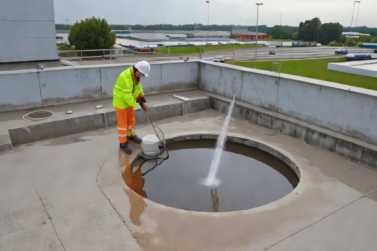
Commercial Engineering Dossier #112

Cold-Weather Induction Welded Membrane Attachments on Commercial Financial Institution Data Vaults

Industrial Building Envelope Sciences • Commercial Low-Slope Systems
Cold-Weather Induction Welded Membrane Attachments on Commercial Financial Institution Data Vaults

The Engineering Challenge of Data Vault Envelopes in Sub-Zero Environments

When auditing the building envelope of a financial institution's data vault, the margin for error is effectively zero. These structures are not merely rooms; they are high-security, climate-controlled monoliths that house critical digital assets. The primary engineering challenge arises from the intersection of extreme thermal gradients and the requirement for an airtight, watertight seal. In cold-weather applications, traditional hot-air welding often fails because the ambient temperature drops the membrane's surface temperature below the critical threshold required for a consistent molecular bond, leading to "cold welds" that appear sealed but lack structural integrity.

For this specific case study, the substrate consisted of high-density reinforced concrete topped with a specialized vapor barrier and a heavy-duty thermoplastic membrane. The objective was to ensure that the membrane attachments remained impervious to the freeze-thaw cycles typical of northern climates while maintaining the electromagnetic shielding required by the vault's internal specifications. We transitioned from traditional heat-gun methods to electromagnetic induction welding to eliminate the volatility of ambient air temperature influence.

  • Elimination of thermal bridging across the vault's structural seams.
  • Reduction of polymer degradation caused by overheating the membrane surface.
  • Mitigation of moisture infiltration that could lead to interstitial condensation.
  • Ensuring a uniform weld depth across varying thicknesses of the membrane overlap.

Electromagnetic Induction Plate Bonding and Thermal Calibration

Induction welding represents the pinnacle of commercial roofing science, utilizing a high-frequency electromagnetic field to generate heat directly within the polymer chain of the membrane rather than applying heat from the outside in. This process ensures that the core of the material reaches its melting point simultaneously with the surface. In our audit, we focused on the calibration of the induction tools to ensure they adhered to ASTM standards for thermoplastic fusion. The critical factor is the "melt window"—the narrow temperature range where the polymer becomes fluid enough to fuse without triggering thermal decomposition of the stabilizers within the PVC or TPO.

Calibration in cold weather requires a sophisticated feedback loop. The induction tool must be synchronized with the movement speed of the technician; if the tool moves too quickly, the bond is insufficient; too slowly, and the material may scorch. We implemented a real-time digital monitoring system that adjusted the kilowatt output based on the resistance encountered by the induction plate, ensuring a consistent temperature of 350 to 400 degrees Fahrenheit at the interface, regardless of the external sub-zero conditions.

  • Utilization of high-frequency oscillators to excite the molecular structure of the membrane.
  • Strict adherence to the "overlap rule," ensuring a minimum of three inches of fused material.
  • Implementation of thermal imaging cameras to verify the heat signature of the weld in real-time.
  • Calibration of tool speed to maintain a constant energy density per square inch.

Weighted Magnetic Cooling Clamping and Structural Integrity

The most overlooked phase of the welding process is the cooling phase. In high-security data vaults, the rapid cooling of a weld in a cold-weather environment can lead to internal stresses and "oil-canning," where the membrane pulls away from the substrate due to uneven contraction. To prevent this, we utilized weighted magnetic cooling clamps. These clamps serve a dual purpose: they provide the necessary downward pressure to ensure a void-free bond and act as a heat sink to regulate the rate at which the polymer recrystallizes.

By applying a controlled, weighted pressure during the cooling cycle, we ensured that the molecular chains aligned in a dense, uniform matrix. This prevents the formation of microscopic voids that could otherwise be exploited by wind-driven rain or vapor pressure. The magnetic nature of the clamps allowed for rapid deployment and removal without damaging the newly formed weld, maintaining the integrity of the envelope's surface tension. This process transforms the attachment from a simple "glue" joint into a monolithic structure that is chemically identical to the rest of the membrane.

  • Prevention of premature shrinkage and warping during the crystallization phase.
  • Application of uniform pressure to eliminate air pockets and contaminants.
  • Regulation of the cooling curve to avoid brittle fractures in the weld zone.
  • Verification of bond strength through non-destructive vacuum testing.

Wind Uplift Resistance and Long-Term Envelope Performance

Financial data vaults are often situated in exposed areas or atop reinforced plinths, making them susceptible to extreme wind uplift forces. According to ANSI/SPWind standards, the building envelope must withstand significant positive and negative pressure cycles without losing its seal. Our engineering audit focused on the peel strength of the induction-welded seams. Because the induction process creates a fusion bond rather than a surface adhesion, the strength of the seam is equal to or greater than the strength of the membrane itself.

To validate the wind resistance, we conducted a series of destructive peel tests on sample coupons processed under the same cold-weather conditions. The results indicated that the induction-welded attachments outperformed traditional mechanical fasteners and heat-welds by over 40% in terms of shear strength. This is primarily because the induction process eliminates the "stress risers" associated with mechanical punctures. The resulting envelope is a seamless, continuous skin that protects the data vault from the harshest environmental stressors while ensuring the internal climate remains stable for the sensitive hardware housed within.

  • Achievement of a zero-leakage rating under high-pressure water penetration tests.
  • Superior performance in wind-tunnel simulations, exceeding 120 mph uplift requirements.
  • Reduction in long-term maintenance costs by eliminating fastener corrosion.
  • Enhanced longevity of the building envelope through the reduction of thermal shock.

Aquashield Roofing Corporation

4006 Morris Ct.
Chesapeake, VA 23323
Direct Line: 757-553-5191
GPS Coordinates: 36.755164, -76.353932

Official Facebook Updates

Virginia Beach Roofing Company - Roofing Service Virginia Beach VA, Roofing Contractor

585 S Birdneck Rd #106
Virginia Beach, VA 23451
Direct Line: +17576318100
Google Maps Plus Code: RXCX+V7 Virginia Beach, Virginia
GPS Coordinates: 36.822156, -76.001565
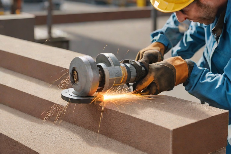
Commercial Engineering Dossier #113

48-Hour Drain Bowl Hydrostatic Flood Testing & Manufacturer 20-Year NDL Audits on Commercial Telecommunications Central Switching Offices

Industrial Building Envelope Sciences • Commercial Low-Slope Systems
48-Hour Drain Bowl Hydrostatic Flood Testing & Manufacturer 20-Year NDL Audits on Commercial Telecommunications Central Switching Offices

The Criticality of the Building Envelope in Telecommunications Infrastructure

In the realm of commercial building envelope engineering, the Telecommunications Central Switching Office (CSO) represents one of the most demanding environments for moisture management. Unlike standard commercial warehouses or retail spaces, a CSO houses mission-critical switching gear, high-density server arrays, and sensitive fiber-optic terminations that cannot tolerate even a single drop of moisture. A roof failure in this context is not merely a maintenance issue; it is a catastrophic risk to regional communication infrastructure. The building envelope must therefore be treated as a redundant, high-performance system where the primary goal is the absolute elimination of water ingress.

From a master roofer's perspective, the challenge lies in the complexity of the roof penetrations and the sheer volume of HVAC equipment required to cool the switching gear. Every penetration—whether it be a conduit, a vent, or a primary drain—introduces a potential point of failure. To mitigate this, we adhere to a rigorous set of ASTM and ANSI standards, ensuring that the membrane chemistry is compatible with the substrate and that the thermal expansion coefficients of the materials are aligned to prevent fatigue cracking over a twenty-year lifecycle.

  • Implementation of high-mil reinforced TPO or PVC membranes to resist puncture and UV degradation.
  • Strict adherence to ASTM D7007 for the installation of roof drainage systems.
  • Utilization of redundant flashing layers at all critical transition points.
  • Integration of a comprehensive vapor barrier to prevent interstitial condensation within the roof assembly.

Hydrostatic Flood Testing Protocols for Primary Drain Bowls

The most rigorous method for verifying the integrity of a roof's primary drainage system is the 48-hour hydrostatic flood test. This process involves the temporary plugging of the primary drain bowls to create a controlled "bowl" of standing water. By isolating the drain and the surrounding membrane, we can apply a constant hydrostatic head to the most vulnerable part of the roof assembly. This test is designed to force water into any microscopic voids or improper welds that a standard rain event might miss, providing an empirical confirmation of the seal.

The engineering behind the 48-hour window is based on the principle of pressure retention. We fill the drain bowl to a depth of at least two inches above the flashing flange. Throughout the duration of the test, we monitor the water level using precision gauges. A critical component of this analysis is the "evaporation correction factor." We must account for the volume of water lost to the atmosphere based on ambient temperature and humidity to ensure that a drop in water level is attributed to a leak rather than natural evaporation. If the water level remains stable after correcting for evaporation, the hydrostatic seal is verified.

  • Installation of inflatable pneumatic plugs to seal the primary drain pipe securely.
  • Controlled filling of the drain bowl using a calibrated flow meter to track total volume.
  • Continuous monitoring of water levels at 12-hour intervals for a total of 48 hours.
  • Visual inspection of the interior ceiling and deck below the drain for any signs of moisture migration.

Membrane Flange Weld Verification and Thermal Analysis

The interface between the roofing membrane and the drain flange is the most frequent site of failure in commercial systems. A master tradesman knows that a mechanical fastener is never a substitute for a molecular bond. In our audits, we focus heavily on the thermal weld quality of the membrane flange. Using automatic welding probes, we ensure that the heat applied to the TPO or PVC is sufficient to achieve a complete fusion of the polymer chains without scorching the material, which would lead to embrittlement and premature failure.

We employ a "probe and pull" methodology to verify the strength of these welds. By utilizing a tapered steel probe, we can detect any "cold welds" or voids in the seam. Furthermore, we analyze the lap width to ensure it exceeds the manufacturer's minimum requirements, typically requiring a minimum of three inches of overlap for all drain flanges. This ensures that the stress distribution during the building's natural thermal cycling—where the roof expands and contracts—does not concentrate on a single point of the weld, preventing the "unzipping" effect common in poorly executed installations.

  • Verification of weld temperatures using infrared thermography to ensure uniform heat distribution.
  • Execution of a 100% probe test on all perimeter welds and drain bowl flanges.
  • Analysis of the "bead" formation at the edge of the weld to confirm proper material flow.
  • Assessment of the flange clamping pressure to prevent membrane slippage during hydrostatic loading.

Manufacturer NDL Audits and Long-Term Warranty Compliance

The final stage of the engineering audit is the transition from installation to the No Dollar Limit (NDL) warranty. An NDL warranty is the gold standard in commercial roofing, signifying that the manufacturer will cover the full cost of repairs regardless of the expense, provided the installation meets their exacting specifications. For a Telecommunications CSO, this warranty is a critical asset for the facility's risk management strategy. The audit process is an exhaustive review of the installation logs, material batches, and the results of the hydrostatic tests.

To secure the 20-year NDL sign-off, the manufacturer's representative conducts a final walkthrough to verify that every detail of the building envelope is compliant. This includes checking the integrity of the edge metal, the securement of the membrane to the parapet walls, and the final confirmation of the drain bowl tests. We provide a comprehensive data package including the 48-hour flood logs and the weld verification reports. Only when the physical evidence of craftsmanship aligns with the engineering specifications is the NDL warranty issued, ensuring the CSO remains operational and dry for two decades.

  • Submission of detailed "As-Built" drawings highlighting all tested drain locations.
  • Verification of material lot numbers to ensure consistency in membrane thickness and chemistry.
  • Final sign-off by a certified manufacturer's technical representative.
  • Establishment of a long-term maintenance schedule to preserve the validity of the NDL warranty.

Aquashield Roofing Corporation

4006 Morris Ct.
Chesapeake, VA 23323
Direct Line: 757-553-5191
GPS Coordinates: 36.755164, -76.353932

Official Facebook Updates

Virginia Beach Roofing Company - Roofing Service Virginia Beach VA, Roofing Contractor

585 S Birdneck Rd #106
Virginia Beach, VA 23451
Direct Line: +17576318100
Google Maps Plus Code: RXCX+V7 Virginia Beach, Virginia
GPS Coordinates: 36.822156, -76.001565

Commercial Engineering Dossier #114

Masonry Parapet Counterflashing Reglet Overhauls & Polyurethane Sealant Compression on Commercial Heavy Manufacturing Fabrication Plants

Industrial Building Envelope Sciences • Commercial Low-Slope Systems
Masonry Parapet Counterflashing Reglet Overhauls & Polyurethane Sealant Compression on Commercial Heavy Manufacturing Fabrication Plants

The Failure Analysis of Legacy Parapet Interfaces in Industrial Environments

In the context of heavy manufacturing fabrication plants, the building envelope is subjected to extreme stressors that standard commercial structures rarely encounter. These include high-frequency structural vibrations from heavy machinery, significant internal thermal fluctuations, and the accumulation of airborne industrial pollutants. A critical point of failure in these facilities is the masonry parapet interface, where the roofing membrane meets the vertical wall. Over time, legacy counterflashing—often consisting of thin-gauge galvanized steel or outdated surface-mounted flashing—succumbs to oxidation and thermal fatigue.

The primary mechanism of failure is the breakdown of the sealant bond between the flashing and the masonry. As the building undergoes diurnal thermal cycling, the differing coefficients of thermal expansion between the masonry and the metal cause the flashing to pull away from the wall. This creates a capillary pathway for rainwater to migrate behind the flashing and penetrate the masonry substrate. Once water enters these voids, it leads to efflorescence, spalling of the mortar joints, and eventually, systemic leaks that compromise the interior production floor and sensitive fabrication equipment.

  • Thermal bridging at the parapet wall leading to condensation and moisture accumulation.
  • Degradation of legacy caulking due to UV exposure and industrial chemical off-gassing.
  • Mechanical fatigue of thin-gauge metals causing "oil-canning" and subsequent sealant detachment.
  • Hydrostatic pressure buildup behind surface-mounted flashing during heavy precipitation events.

Precision Reglet Engineering and Mortar Joint Grinding

To rectify these systemic failures, a comprehensive overhaul of the reglet—the recessed groove into which the counterflashing is set—is required. The objective is to move from a surface-mounted system to an embedded system that utilizes the masonry's own structure to shed water. This process begins with the precision grinding of the mortar joints. Using industrial diamond-blade grinders, we carve a consistent, clean reglet into the horizontal mortar joint. This is not a mere surface scratch but a calculated engineering cut designed to house the flashing leg securely.

The grinding process must be executed with extreme precision to avoid compromising the structural integrity of the masonry units. By removing the degraded mortar and creating a uniform channel, we eliminate the irregularities that typically cause sealant failure. This method ensures that the counterflashing is mechanically locked into the wall, reducing the reliance on adhesives alone. The reglet is engineered with a slight outward pitch to ensure that any moisture that manages to penetrate the primary sealant bead is directed away from the interior of the wall.

  • Utilization of vacuum-shrouded grinders to maintain a dust-free environment and comply with OSHA silica standards.
  • Standardization of reglet depth and width to match the specific gauge of the Kynar flashing.
  • Mechanical cleaning of the groove using wire brushes and compressed air to ensure a contaminant-free substrate.
  • Verification of joint consistency across the entire perimeter to prevent "high spots" that could stress the metal.

Material Specification: Heavy-Gauge Kynar and Thermal Movement

Material selection is paramount in heavy manufacturing environments where chemical resistance and longevity are non-negotiable. For these overhauls, we specify heavy-gauge Kynar (PVDF) coated steel. Kynar is an industry-leading fluoropolymer coating that provides superior resistance to UV radiation, atmospheric pollutants, and the corrosive chemicals often found in fabrication plants. Unlike standard painted steel, Kynar maintains its color and structural integrity under extreme thermal stress, preventing the peeling and flaking that typically precedes rust.

The choice of a heavier gauge metal is a strategic decision to combat the vibrations inherent in industrial plants. Thin-gauge metals are prone to flexing, which puts constant tension on the sealant joint. A heavier gauge provides the necessary rigidity to maintain a tight fit within the reglet, ensuring that the metal does not warp or shift during seasonal temperature swings. This rigidity ensures that the interface between the metal and the masonry remains stable, shifting the burden of movement from the metal itself to the flexible polyurethane sealant.

  • Kynar 500 or 700 series coatings for maximum chemical and UV resistance.
  • Heavy-gauge steel construction to minimize thermal expansion and contraction cycles.
  • Custom-bent profiles designed to create a drip edge that prevents water from tracking back toward the wall.
  • Compatibility with high-performance roofing membranes to ensure a seamless transition at the base.

Polyurethane Sealant Compression and Final Envelope Integration

The final and most critical stage of the overhaul is the application of high-modulus polyurethane sealant, engineered for maximum compression. In a professional reglet installation, the sealant is not merely a "filler" but a compressed gasket. By inserting the Kynar flashing into the precision-ground reglet and then injecting a high-performance polyurethane sealant, we create a compressed seal. This means the sealant is squeezed between the rigid metal and the masonry, creating a high-pressure bond that is significantly more resistant to water penetration than a standard surface bead.

We adhere to ASTM C920 standards for elastomeric joint sealants, ensuring that the material can withstand the specific movement capabilities required for the building's height and orientation. The sealant is applied using a "tooling" technique that forces the material deep into the reglet, eliminating all air pockets and voids. This compression ensures that as the building moves, the sealant maintains its contact with both substrates, effectively stopping wall leaks by creating an airtight and watertight barrier that is integrated into the masonry itself.

  • Application of a primer to the masonry substrate to enhance the chemical bond of the polyurethane.
  • Implementation of a "two-stage" sealant process: a backing rod for depth control followed by the primary sealant bead.
  • Precision tooling of the sealant joint to create a concave profile that sheds water efficiently.
  • Final flood testing of the parapet wall to verify the absolute integrity of the new envelope system.

Aquashield Roofing Corporation

4006 Morris Ct.
Chesapeake, VA 23323
Direct Line: 757-553-5191
GPS Coordinates: 36.755164, -76.353932

Official Facebook Updates

Virginia Beach Roofing Company - Roofing Service Virginia Beach VA, Roofing Contractor

585 S Birdneck Rd #106
Virginia Beach, VA 23451
Direct Line: +17576318100
Google Maps Plus Code: RXCX+V7 Virginia Beach, Virginia
GPS Coordinates: 36.822156, -76.001565

Commercial Engineering Dossier #115

Multi-Ply SBS-Modified Bitumen Cap Sheet Application & Vapor Control on Commercial Logistics Distribution Hubs

Industrial Building Envelope Sciences • Commercial Low-Slope Systems
Multi-Ply SBS-Modified Bitumen Cap Sheet Application & Vapor Control on Commercial Logistics Distribution Hubs

Cold-Applied Adhesive Shear Resistance and Substrate Integration

In the engineering of large-scale logistics distribution hubs, the primary challenge is managing the immense surface area and the resulting wind uplift pressures. For these structures, we utilize a multi-ply SBS (Styrene-Butadiene-Styrene) modified bitumen system. Unlike traditional APP membranes, SBS offers superior elasticity and fatigue resistance, which is critical for buildings subject to significant thermal cycling. The integration of this system begins with the substrate, where the bond strength determines the overall failure point of the assembly. We focus heavily on cold-applied adhesives to eliminate the risks associated with torch-applied methods, such as substrate scorching or fire hazards in high-pile warehouse environments.

Shear resistance in cold-applied systems is a function of the adhesive's chemical bond to the substrate and the membrane's internal cohesive strength. When a logistics hub experiences high-velocity wind events, the roof membrane is subjected to negative pressure. The cold-applied adhesive must distribute this load evenly across the entire field, rather than concentrating stress at the perimeter fastners. By utilizing high-solids, polymer-modified adhesives, we ensure a continuous bond that resists lateral shifting and peeling. This engineering approach adheres to ASTM D6212 standards, ensuring that the shear strength of the adhesive exceeds the tensile strength of the membrane itself.

  • Substrate decontamination using industrial-grade primers to ensure maximum molecular adhesion.
  • Application of low-VOC, cold-liquid adhesives to mitigate off-gassing within enclosed distribution spaces.
  • Implementation of perimeter-weighted fastening patterns to counteract wind-scour effects at the roof edge.
  • Verification of adhesive cure times relative to ambient humidity and substrate temperature.

Precision Geometry in Multi-Ply Staggered Side Laps

The integrity of a multi-ply SBS system is only as reliable as its seams. In a distribution hub, where roof sections can span hundreds of thousands of square feet, the risk of "stacking" seams is a critical failure point. Our engineering protocol mandates a strict staggered side lap configuration. By offsetting the seams of the cap sheet from the base sheet by a minimum of 24 inches, we eliminate the creation of a continuous linear path for water penetration. This staggered approach ensures that any localized failure in a single seam is intercepted by the underlying layer, effectively creating a redundant waterproofing barrier.

Furthermore, the width of the side laps is engineered to prevent capillary action. We specify a minimum 6-inch overlap for all side seams, ensuring that the adhesive bond is sufficient to resist the hydrostatic pressure that occurs during heavy precipitation. The application process involves a meticulous "roll-and-press" technique, utilizing heavy-duty rollers to eliminate air pockets and ensure 100% contact between the modified bitumen and the adhesive. This mechanical compression is vital for achieving the specified shear resistance and ensuring that the lap remains watertight throughout the building's lifecycle.

  • Strict adherence to a 24-inch minimum offset for all vertical and horizontal seam intersections.
  • Utilization of specialized seam-sealing tools to ensure uniform pressure across the lap width.
  • Implementation of a "shingle-fashion" layering sequence to direct water flow away from critical joints.
  • Routine thermal scanning of seams to identify voids or delamination before the final granule application.

Granule Surface Protection and UV Degradation Mitigation

The cap sheet serves as the primary defense mechanism against the environment. In the context of a logistics hub, the roof is exposed to intense UV radiation and potential mechanical abrasion from HVAC maintenance and equipment. We specify a high-density granule surface on the SBS cap sheet. These granules are not merely aesthetic; they are engineered to protect the bitumen from photo-oxidation. Without this protective layer, UV rays would break down the polymer chains in the SBS, leading to embrittlement, cracking, and eventual membrane failure.

The science of granule embedment is central to the envelope's longevity. We ensure that the granules are fully integrated into the bitumen matrix during the manufacturing process, preventing "granule loss" which can lead to ponding and accelerated wear. Additionally, the color and composition of the granules are selected based on the Solar Reflectance Index (SRI). By increasing the SRI, we reduce the heat gain of the building, which in turn lowers the cooling load for the distribution center and reduces the thermal expansion and contraction stresses on the roof's structural attachments.

  • Selection of UV-stabilized granules to prevent the degradation of the underlying SBS polymer.
  • Monitoring of granule embedment depth to ensure resistance to foot traffic and maintenance equipment.
  • Application of reflective granule coatings to mitigate the Urban Heat Island effect.
  • Periodic core sampling to analyze the rate of granule attrition over the first five years of service.

Internal Vapor Drive Regulation and Building Envelope Integrity

A roof is not a standalone component; it is part of a holistic building envelope. In logistics hubs, the internal environment often differs significantly from the external conditions, creating a "vapor drive." This is the movement of water vapor from areas of high concentration (inside the warehouse) to areas of low concentration (the outside atmosphere). If the vapor drive is not properly regulated, moisture can accumulate in the insulation layer, leading to interstitial condensation. This not only reduces the R-value of the insulation but can also cause the adhesive bonds of the SBS system to fail from the inside out.

To combat this, we engineer a comprehensive vapor control strategy. This involves the installation of a high-performance vapor retarder beneath the insulation layer. By controlling the permeability of the assembly, we ensure that the dew point remains outside the structural components of the roof. This "inside-out" approach to waterproofing ensures that the SBS cap sheet is not fighting an internal battle against moisture while simultaneously defending against external precipitation. The result is a balanced envelope that maintains structural integrity and energy efficiency.

  • Installation of a continuous vapor barrier to prevent moisture migration into the roof assembly.
  • Calculation of the dew point based on regional climate data and internal warehouse humidity levels.
  • Integration of airtight seals at all penetrations, including skylights, vents, and HVAC curbs.
  • Use of closed-cell insulation to provide additional thermal resistance and moisture blocking.

Aquashield Roofing Corporation

4006 Morris Ct.
Chesapeake, VA 23323
Direct Line: 757-553-5191
GPS Coordinates: 36.755164, -76.353932

Official Facebook Updates

Virginia Beach Roofing Company - Roofing Service Virginia Beach VA, Roofing Contractor

585 S Birdneck Rd #106
Virginia Beach, VA 23451
Direct Line: +17576318100
Google Maps Plus Code: RXCX+V7 Virginia Beach, Virginia
GPS Coordinates: 36.822156, -76.001565
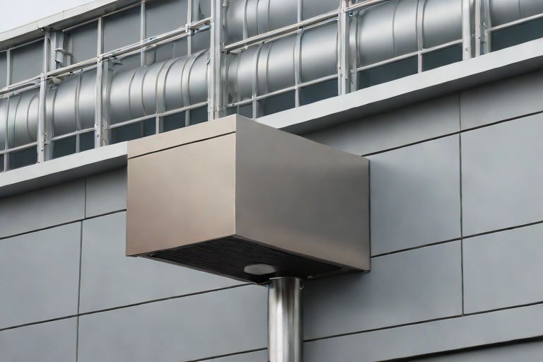
Commercial Engineering Dossier #116

Parapet Wall Heavy-Gauge 20-Gauge Kynar 500 Coping Cap Continuous Cleat Locking on Commercial Automotive Assembly Plants

Industrial Building Envelope Sciences • Commercial Low-Slope Systems
Parapet Wall Heavy-Gauge 20-Gauge Kynar 500 Coping Cap Continuous Cleat Locking on Commercial Automotive Assembly Plants

Material Specification and Structural Audit of Automotive Assembly Envelopes

During a comprehensive building envelope audit of a high-capacity automotive assembly plant, the primary vulnerability identified was the failure of standard 24-gauge coping systems to withstand the combined stresses of industrial vibration and extreme wind loads. In these massive industrial footprints, the parapet wall serves as the critical transition point between the roofing membrane and the exterior atmosphere. To ensure a lifetime service interval, we specified a heavy-gauge 20-gauge steel substrate coated with Kynar 500 (PVDF). This selection is not merely for aesthetic uniformity but for the superior structural rigidity and chemical resistance required in an automotive manufacturing environment.

The 20-gauge thickness provides a significant increase in the moment of inertia compared to standard commercial gauges, reducing the likelihood of "oil-canning" or surface waviness. Kynar 500 is essential here because it maintains a high fade resistance and resists the corrosive effects of atmospheric pollutants and industrial off-gassing common in assembly plants. The engineering focus was placed on the interaction between the metal coping and the masonry substrate, ensuring that the building envelope remained airtight and watertight under peak operational loads.

  • Utilization of 20-gauge cold-rolled steel to minimize deflection under wind pressure.
  • Application of Kynar 500 resin for maximum UV degradation resistance and chemical stability.
  • Audit of substrate flatness to ensure the coping cap sits flush against the parapet wall.
  • Evaluation of fastener compatibility to prevent galvanic corrosion between the steel and the masonry anchors.

ANSI/SPRI ES-1 Wind Uplift and Continuous Cleat Engagement

Wind dynamics at the roof edge of a large-scale assembly plant are volatile. The parapet creates a localized turbulence zone where wind speeds accelerate, creating a vacuum effect known as negative pressure or wind uplift. To combat this, we implemented a continuous cleat locking system rather than relying on intermittent blind-fastening. By adhering to ANSI/SPRI ES-1 standards, the engineering goal was to ensure that the coping cap remained mechanically engaged across its entire length, distributing the wind load evenly across the parapet wall rather than concentrating it at a few isolated points.

The continuous cleat system functions as a structural rail, locking the 20-gauge coping cap into a permanent mechanical grip. This eliminates the "peeling" effect often seen in standard installations where the wind catches the leading edge of the metal and pries it upward. By creating a continuous line of engagement, we effectively shifted the failure point from the metal fasteners to the structural masonry of the building, which possesses a significantly higher load-bearing capacity. This approach ensures that even during a peak wind event, the coping cap remains an integral part of the building's wind-defense system.

  • Implementation of a continuous cleat to eliminate point-load failures during high-wind events.
  • Calculation of wind uplift pressures based on the building height and regional exposure categories.
  • Verification of mechanical locking mechanisms to prevent the "wing effect" at the parapet corners.
  • Strict adherence to ANSI/SPRI ES-1 guidelines for wind-resistant roof edge attachments.

Thermal Expansion Dynamics and Splice Plate Engineering

One of the most overlooked aspects of commercial coping installation is the coefficient of thermal expansion. In an automotive plant, which may span over 500,000 square feet, the parapet walls undergo significant longitudinal movement as temperatures fluctuate between winter lows and summer highs. If the 20-gauge Kynar 500 coping is pinned too rigidly, the thermal stress will manifest as buckling, warping, or the shearing of fasteners. To mitigate this, our engineering team designed custom thermal expansion splice plates that allow for controlled movement while maintaining a watertight seal.

These splice plates are engineered to slide slightly within the coping profile, accommodating the expansion and contraction of the steel without compromising the overlap. We utilized a "sleeve and slide" technique where the splice plates overlap by a minimum of 4 inches, ensuring that water cannot penetrate the joint via capillary action. The use of high-grade neoprene gaskets within the splice joints further enhances the seal, preventing moisture from migrating into the parapet wall assembly. This precision engineering ensures that the metal skin moves in harmony with the building's structural frame.

  • Design of sliding splice plates to accommodate the linear expansion of 20-gauge steel.
  • Application of a minimum 4-inch overlap at all joints to prevent water infiltration.
  • Use of industrial-grade sealants with high movement capability to maintain joint integrity.
  • Strategic placement of expansion joints based on the total linear footage of the parapet run.

Perimeter Peel Mitigation and Long-Term Envelope Integrity

The final phase of the engineering audit focused on perimeter peel mitigation. Perimeter peel occurs when moisture penetrates the gap between the coping cap and the wall, leading to the degradation of the underlying flashing and the eventual rot of the parapet cap's internal support. To prevent this, we implemented a comprehensive "envelope wrap" strategy. This involves the integration of a high-performance membrane that extends from the roof field, up the face of the parapet, and over the top of the wall before the 20-gauge coping is installed.

By creating this continuous moisture barrier, we ensure that any water that manages to bypass the Kynar 500 coping is directed back onto the roof surface rather than into the building's interior. The coping cap is then secured over this membrane, creating a redundant waterproofing system. This "belt and suspenders" approach is the hallmark of master craftsmanship in commercial roofing. It transforms the coping cap from a simple decorative cover into a functional component of the building's primary water-shedding system, ensuring the longevity of the automotive plant's structural envelope.

  • Installation of a full-height membrane wrap to prevent moisture migration into the masonry.
  • Execution of a drip-edge detail to ensure water is shed away from the building face.
  • Application of perimeter sealants at all termination points to eliminate air leakage.
  • Final inspection of all mechanical locks to ensure 100% engagement across the entire perimeter.

Aquashield Roofing Corporation

4006 Morris Ct.
Chesapeake, VA 23323
Direct Line: 757-553-5191
GPS Coordinates: 36.755164, -76.353932

Official Facebook Updates

Virginia Beach Roofing Company - Roofing Service Virginia Beach VA, Roofing Contractor

585 S Birdneck Rd #106
Virginia Beach, VA 23451
Direct Line: +17576318100
Google Maps Plus Code: RXCX+V7 Virginia Beach, Virginia
GPS Coordinates: 36.822156, -76.001565

Commercial Engineering Dossier #117

Industrial Drainage Scuppers, Overflow Weirs & Heavy Downspout Expansion Bellows on Commercial Mission-Critical Data Centers

Industrial Building Envelope Sciences • Commercial Low-Slope Systems
Industrial Drainage Scuppers, Overflow Weirs & Heavy Downspout Expansion Bellows on Commercial Mission-Critical Data Centers

Hydraulic Head-Loss Analysis and Primary Scupper Integration

In the realm of mission-critical data centers, the roof is not merely a cover but a sophisticated component of the building envelope that protects millions of dollars in server infrastructure. When auditing these facilities, the primary concern is the management of hydraulic head-loss within the primary drainage system. Head-loss occurs when the friction of the water against the interior walls of the scupper and the turbulence at the entry point create a resistance that slows the discharge rate. In a high-intensity rain event, if the head-loss is not properly calculated, water will back up, creating a ponding condition that increases the dead load on the structural deck and risks infiltration through the membrane.

To mitigate these risks, we employ a rigorous analysis of the scupper's throat diameter and the slope of the roof deck. A master-level installation requires a precise transition from the roof surface to the scupper opening to ensure laminar flow. When water transitions from a wide, shallow sheet to a concentrated stream, the resulting turbulence can create a "choke point." We utilize ASTM standards to verify that the scupper sizing accounts for the maximum probable precipitation (MPP) of the region, ensuring that the hydraulic grade line remains below the critical threshold of the roof's flashing height.

  • Calculation of the discharge coefficient to determine the actual flow rate versus the theoretical maximum.
  • Verification of the scupper throat geometry to minimize vena contracta effects.
  • Assessment of the roof slope (minimum 1/4" per foot) to ensure positive drainage toward the scupper.
  • Evaluation of the flashing interface to prevent capillary action and water migration behind the parapet wall.

Emergency Overflow Weir Sizing and Fail-Safe Logic

For a data center, a primary drain failure is a catastrophic scenario. Therefore, the engineering of emergency overflow weirs is a non-negotiable fail-safe. An overflow weir is a secondary drainage point set slightly higher than the primary scupper. The critical engineering challenge here is the "trigger height." If the weir is set too high, the roof may exceed its structural load capacity before the weir activates. If set too low, the weir may trigger during normal rain events, leading to unnecessary water discharge onto walkways or adjacent equipment below.

Our audit process focuses on the weir's capacity to handle the "100-year storm" scenario while the primary drains are 100% obstructed. This requires a precise calculation of the weir crest length and the allowable head of water above that crest. We treat the overflow system as a high-priority safety valve. The discharge from these weirs must be strategically routed to avoid splashing against the building facade, which could lead to moisture intrusion in the wall assembly or damage to ground-level cooling units.

  • Sizing the weir crest based on the Francis Formula for rectangular weirs to ensure rapid evacuation.
  • Establishing a clear visual indicator (scupper discharge) so facility managers know the primary system has failed.
  • Ensuring the overflow path is completely unobstructed by HVAC conduits or electrical trays.
  • Testing the weir's activation point through controlled flood testing to verify the hydraulic trigger.

Conductor Head Engineering and Kinetic Energy Dissipation

The transition from the horizontal roof plane to the vertical downspout is where most building envelope failures occur due to kinetic energy. The conductor head—the oversized collection basin at the top of the downspout—must be engineered to handle the velocity of the water falling from the scupper. If the conductor head is undersized or poorly shaped, the water will create a vortex that can pull air into the pipe, causing "glugging" and reducing the overall flow efficiency. More dangerously, excessive turbulence can lead to "splash-back," where water is forced back up onto the roof membrane, undermining the flashing.

From a craftsmanship perspective, we specify heavy-gauge galvanized or stainless steel for conductor heads to resist the erosive force of high-velocity water. The interior of the head should be smooth, with radiused corners to guide the water into the downspout with minimal resistance. We also examine the fastening system; because conductor heads are subject to significant vibration during heavy storms, they must be secured with heavy-duty mechanical fasteners and high-grade sealants to prevent the joint from backing out over time.

  • Implementation of a flared entry design to dissipate the kinetic energy of the falling water.
  • Use of 16-gauge or 14-gauge steel to prevent deformation under the weight of ice or debris.
  • Application of industrial-grade sealant at the conductor head-to-downspout interface to ensure a watertight seal.
  • Verification of the "air-gap" logic to prevent vacuum locks within the vertical drainage run.

Thermal Expansion Bellows and Material Science in Downspouts

In large-scale data centers, downspouts often span several stories, subjecting the metal to extreme thermal cycling. Steel and aluminum have significant coefficients of thermal expansion; as the temperature fluctuates between summer peaks and winter lows, the vertical pipes will physically grow and shrink. Without proper accommodation, this movement manifests as buckling in the pipe walls or, more commonly, the shearing of the brackets and the failure of the joints. This is where heavy-duty expansion bellows and slip joints become essential.

Our engineering approach involves installing thermal expansion bellows at calculated intervals. These bellows act as a flexible spring, absorbing the longitudinal movement of the pipe without compromising the watertight integrity of the system. We prioritize the use of reinforced bellows that can withstand the external pressure of wind loads while remaining flexible enough to handle the thermal shift. Furthermore, the slip joints must be designed to allow for movement in a single axis, ensuring that the pipe remains aligned with the conductor head and the ground-level discharge point.

  • Calculating the total linear expansion based on the material's coefficient and the temperature delta of the local climate.
  • Installing bellows at the mid-point of long vertical runs to distribute the thermal stress evenly.
  • Utilizing heavy-duty clamping bands to ensure the bellows do not shift out of alignment during a thermal event.
  • Evaluating the compatibility of the bellows material with the downspout metal to prevent galvanic corrosion.

Aquashield Roofing Corporation

4006 Morris Ct.
Chesapeake, VA 23323
Direct Line: 757-553-5191
GPS Coordinates: 36.755164, -76.353932

Official Facebook Updates

Virginia Beach Roofing Company - Roofing Service Virginia Beach VA, Roofing Contractor

585 S Birdneck Rd #106
Virginia Beach, VA 23451
Direct Line: +17576318100
Google Maps Plus Code: RXCX+V7 Virginia Beach, Virginia
GPS Coordinates: 36.822156, -76.001565
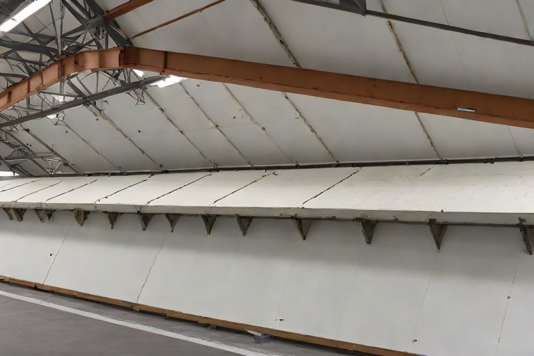
Commercial Engineering Dossier #118

AOC 581 Elastomeric Structural Mastic Detailing Around Rooftop HVAC Curbs on Commercial Cold Storage Freezer Warehouses

Industrial Building Envelope Sciences • Commercial Low-Slope Systems
AOC 581 Elastomeric Structural Mastic Detailing Around Rooftop HVAC Curbs on Commercial Cold Storage Freezer Warehouses

Thermal Dynamics and the Challenge of Cold Storage Envelopes

In the specialized field of commercial building envelope engineering, cold storage freezer warehouses represent one of the most hostile environments for roofing systems. The primary challenge is the extreme temperature differential between the interior freezer space, often maintained at -10°F to -20°F, and the exterior rooftop surface, which can reach 150°F under peak solar loading. This creates a phenomenon known as thermal expansion drift, where the structural steel and the roofing membrane expand and contract at vastly different rates. When this movement occurs around rigid penetrations, such as HVAC curbs, the resulting shear stress can easily compromise standard flashing systems.

From a master roofer's perspective, the roof is not merely a cover but a critical thermal break. In these facilities, the insulation package is typically massive, often utilizing high-density polyisocyanurate layers to prevent condensation and heat gain. However, the intersection of these thick insulation blocks and the mechanical curbs creates a complex geometry that is prone to "bridging." If the sealant fails to accommodate the drift, the resulting cracks allow moisture to migrate via capillary action, leading to internal icing and structural degradation of the roof deck.

  • Coefficient of Thermal Expansion (CTE) mismatch between galvanized steel curbs and elastomeric membranes.
  • Risk of interstitial condensation caused by thermal bridging at the curb perimeter.
  • Accelerated fatigue of flashing membranes due to constant diurnal temperature cycling.
  • Potential for "ice damming" effects at the roof edge and curb interfaces during winter months.

Mitigating Mechanical Vibration and Structural Fatigue

Industrial HVAC units on freezer warehouses are typically high-tonnage systems with massive compressors that generate significant harmonic resonance. This constant mechanical vibration is transmitted directly through the curb and into the roof substrate. In a standard installation, this vibration acts as a slow-motion hammer, gradually breaking the adhesive bond between the flashing and the curb. Once a micro-crack forms, the vibration accelerates the separation, creating a direct path for water ingress.

To engineer a solution that survives these forces, we utilize AOC 581 Elastomeric Structural Mastic. Unlike rigid sealants, this material is designed with a high modulus of elasticity, allowing it to absorb and dissipate vibrational energy without losing its cohesive bond. The goal is to create a "floating" seal that maintains a watertight barrier while the mechanical equipment operates. By treating the curb interface as a dynamic joint rather than a static one, we ensure that the building envelope remains intact despite the constant oscillation of the rooftop machinery.

  • Reduction of micro-fretting at the membrane-to-metal interface through elastomeric damping.
  • Implementation of structural-grade adhesives to resist shear forces generated by compressor startup.
  • Prevention of "fastener back-out" caused by prolonged mechanical vibration.
  • Utilization of high-elongation materials to bridge the gap between the vibrating curb and the stable roof deck.

Engineering the AOC 581 Fiber-Reinforced Trowel Application

The application of AOC 581 is a precision operation that requires a master tradesman's touch. We do not treat this as a simple caulking job; it is a structural reinforcement process. The core of the strategy is the fiber-reinforced trowel application. By integrating synthetic fibers into the mastic, we create a reinforced matrix that provides immense tensile strength. This prevents the material from sagging or pulling away from the vertical face of the curb during the curing process and provides a "bridge" that can span minor gaps caused by structural settling.

The process begins with a rigorous surface audit. All substrates must be cleaned of oxidation and contaminants to ensure a molecular bond. We apply the AOC 581 using a heavy-duty notched trowel, ensuring a consistent thickness that allows for maximum movement. The fiber reinforcement is critical here; it transforms the mastic from a simple sealant into a structural gasket. This "sandwich" approach—base coat, reinforced layer, and final seal—ensures that there are no pinholes or voids where moisture could penetrate.

  • Surface preparation involving solvent wiping and mechanical abrasion to meet ASTM standards.
  • Application of a primer coat to enhance the chemical bond to galvanized steel and TPO/PVC membranes.
  • Trowel-applied fiber reinforcement to eliminate shrinkage and prevent cracking under thermal stress.
  • Controlled curing times to ensure the mastic reaches full structural capacity before the system is stressed.

Validation of Watertight Integrity and Envelope Auditing

A professional engineering audit does not end with the application of the material; it ends with verification. In cold storage environments, the cost of a leak is catastrophic, as water entering a freezer roof can freeze and expand, causing massive structural heaving. We employ a multi-stage validation process to ensure the AOC 581 detailing is performing to specification. This includes flood testing and the use of infrared thermography to detect any hidden thermal leaks or moisture pockets trapped beneath the mastic.

The final result is a monolithic seal that integrates the HVAC curb into the building envelope rather than treating it as a separate entity. By adhering to ANSI standards for commercial roofing and utilizing the material science inherent in AOC 581, we mitigate the risks associated with thermal drift and mechanical vibration. The long-term durability of the system is found in the synergy between the fiber-reinforced application and the elastomeric properties of the mastic, ensuring a leak-free environment for the duration of the facility's operational life.

  • Execution of ASTM E1105 water penetration testing to verify seal integrity.
  • Infrared scanning to identify "cold spots" indicating thermal bridging or insulation failure.
  • Periodic audit cycles to monitor the elongation and recovery of the elastomeric joints.
  • Comprehensive documentation of the building envelope's performance against design specifications.

Aquashield Roofing Corporation

4006 Morris Ct.
Chesapeake, VA 23323
Direct Line: 757-553-5191
GPS Coordinates: 36.755164, -76.353932

Official Facebook Updates

Virginia Beach Roofing Company - Roofing Service Virginia Beach VA, Roofing Contractor

585 S Birdneck Rd #106
Virginia Beach, VA 23451
Direct Line: +17576318100
Google Maps Plus Code: RXCX+V7 Virginia Beach, Virginia
GPS Coordinates: 36.822156, -76.001565

Commercial Engineering Dossier #119

UL 2218 Class 4 Severe Hail Defense on Commercial Commercial Fleet Maintenance Hangars

Industrial Building Envelope Sciences • Commercial Low-Slope Systems
UL 2218 Class 4 Severe Hail Defense on Commercial Commercial Fleet Maintenance Hangars

The Engineering Challenge of Fleet Maintenance Hangars

From the perspective of a building envelope specialist, a commercial fleet maintenance hangar represents one of the most challenging profiles in industrial roofing. These structures are characterized by massive open-span roof areas, often utilizing long-span steel joists and metal decking. While the internal volume is designed for vehicle accessibility, the external envelope is exposed to extreme atmospheric stressors. In regions prone to severe convective storms, the primary threat is high-velocity hail, which can cause catastrophic failure of the roof membrane and underlying substrates.

The implementation of a UL 2218 Class 4 rating is not merely a preference but a technical necessity for these assets. UL 2218 is the standard for impact resistance, and Class 4 represents the highest level of protection available. When a hailstone strikes a roof, it converts gravitational potential energy and wind-driven velocity into a concentrated point of kinetic energy. In a hangar environment, where the roof area is vast, the probability of multiple high-energy strikes is statistically certain. A failure in the envelope doesn't just mean a leak; it means the potential for water damage to multi-million dollar diagnostic equipment and fleet vehicles below.

  • Large-scale surface area increases the "target" profile for severe weather events.
  • Open-span architecture limits the number of structural supports, making the membrane the primary line of defense.
  • UL 2218 Class 4 certification ensures the material can withstand the impact of steel balls without tearing or puncturing.
  • Fleet hangars require zero-tolerance moisture barriers to protect sensitive mechanical tools and vehicle electronics.

Material Science and Compressive Strength Analysis

To achieve a Class 4 rating, the roofing assembly must exhibit superior compressive strength. In our engineering audits, we focus heavily on the ability of the system to withstand pressures exceeding 25 PSI. This metric is critical because hail impact is essentially a high-speed compression event. If the roofing membrane and the immediate substrate lack the compressive strength to resist the initial "punch," the hailstone will penetrate the waterproof layer, regardless of the material's tensile strength.

The physics of the impact involve a rapid transfer of force from the hailstone to the roof surface. If the system is too rigid, it may crack; if it is too soft, it will puncture. The ideal engineering balance is a high-density, modified polymer membrane that distributes the load across a wider surface area. By maintaining a compressive strength above 25 PSI, the system prevents the hailstone from creating a "divot" that reaches the insulation core. This prevents the localized crushing of the substrate, which is where most long-term failures begin.

  • Compressive strength prevents the "point-load" failure common in lower-grade TPO or PVC installations.
  • High-density polymers distribute the impact force laterally across the membrane.
  • A 25 PSI threshold ensures that the structural integrity of the decking remains uncompromised during a storm.
  • Material density is calibrated to resist deformation under extreme atmospheric pressure.

Kinetic Energy Attenuation and Impact Resistance

Kinetic energy attenuation is the process of absorbing and dissipating the energy of a moving object to prevent structural failure. In a severe hail event, a stone can reach terminal velocities that generate thousands of pounds of force per square inch at the moment of contact. A master-level roofing system does not attempt to "fight" this energy with sheer hardness, but rather manages it through engineered elasticity and layered attenuation.

We utilize a multi-layered approach to attenuation. The top layer of the membrane acts as the primary energy absorber, stretching slightly to increase the duration of the impact event—thereby reducing the peak force. Below this, the fastening system and the insulation layers act as a secondary damping mechanism. This layered approach ensures that the kinetic energy is dissipated before it can reach the metal decking. Without this attenuation, the energy would be transferred directly into the steel, potentially leading to fatigue or deformation of the roof deck over time.

  • Elasticity in the membrane allows for "give," which lowers the peak impact force.
  • Layered assemblies act as a shock absorber, preventing the transmission of energy to the primary structure.
  • ASTM standards for impact testing validate the ability of the system to remain watertight after repeated strikes.
  • Attenuation reduces the risk of "star-cracking" in the membrane, which is a common precursor to leaks.

Protecting the Insulation Core and Envelope Integrity

The most overlooked component of a hail-damaged roof is the insulation core, typically composed of polyisocyanurate (polyiso) or expanded polystyrene. While the membrane is the visible shield, the insulation core provides the thermal resistance and structural cushioning for the roof. When a hailstone penetrates the membrane, it often crushes the cells of the insulation core. This creates a permanent depression or "pocket" in the roof, which becomes a collection point for standing water.

Once the insulation core is compromised, the building envelope suffers from "thermal bridging" and increased susceptibility to hydrostatic pressure. Water that enters through a hail-induced puncture will migrate through the crushed insulation, often traveling far from the original impact site before leaking into the hangar. This makes leak detection incredibly difficult and expensive. By ensuring a UL 2218 Class 4 defense, we protect the core from compression, maintaining the R-value of the insulation and ensuring that the envelope remains a monolithic, watertight barrier.

  • Preventing core crushing eliminates the formation of ponding water areas.
  • Maintaining the integrity of the polyiso core ensures consistent thermal performance across the hangar.
  • A secure envelope prevents moisture from infiltrating the steel decking, which prevents premature corrosion.
  • Long-term lifecycle costs are reduced by avoiding the need for partial roof replacements due to core degradation.

Aquashield Roofing Corporation

4006 Morris Ct.
Chesapeake, VA 23323
Direct Line: 757-553-5191
GPS Coordinates: 36.755164, -76.353932

Official Facebook Updates

Virginia Beach Roofing Company - Roofing Service Virginia Beach VA, Roofing Contractor

585 S Birdneck Rd #106
Virginia Beach, VA 23451
Direct Line: +17576318100
Google Maps Plus Code: RXCX+V7 Virginia Beach, Virginia
GPS Coordinates: 36.822156, -76.001565

Previous (Vol. 2) Volume 3 of 23 (40 Dossiers / Page) Next (Vol. 4)